Self-calibration gas chamber and distributed optical fiber methane sensing system

A distributed optical fiber and sensing system technology, applied in the direction of color/spectral characteristic measurement, etc., can solve the problems of increasing system cost, inability to realize accurate calibration of a single measurement channel, reducing system capacity, etc., and achieve system cost reduction, simple structure, Effect of increasing system capacity

Inactive Publication Date: 2017-10-10
CHINA COAL TECH & ENG GRP CHONGQING RES INST CO LTD
View PDF9 Cites 5 Cited by
  • Summary
  • Abstract
  • Description
  • Claims
  • Application Information

AI Technical Summary

Problems solved by technology

[0004] The existing self-calibration gas chamber is independent of the measurement channel and occupies one optical path signal, which reduces the system capacity and increases the system cost
In addition, the self-calibration function of multiple measurement channels is uniformly adjusted by the same calibration signal source, which cannot realize the precise calibration function of a single measurement channel

Method used


Image

  • Self-calibration gas chamber and distributed optical fiber methane sensing system
  • Self-calibration gas chamber and distributed optical fiber methane sensing system

Examples


Embodiment 1

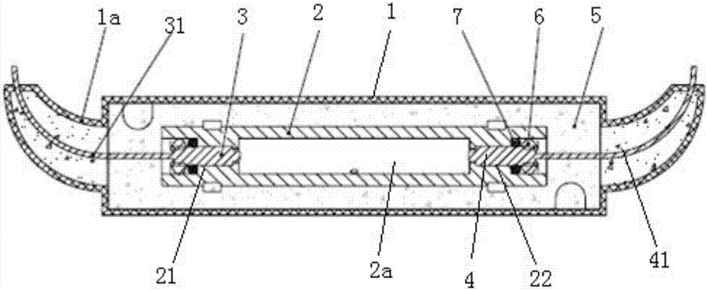
[0023] Such as figure 1 Shown: the self-calibration gas chamber of this embodiment includes a potting box 1 and a shell 2 potted and fixed in the potting box 1, an optical fiber collimator I3 and an optical fiber collimator II4, the shell 2 is provided with There is a gas accommodating cavity 2a for accommodating self-calibration gas and its left and right sides are symmetrically provided with a fixing seat I21 and a fixing seat II22, an optical fiber collimator I3 fixed in the fixing seat I21 and an optical fiber collimator fixed in the fixing seat II22 The pigtails Ⅰ31 of the fiber collimator Ⅰ3 and the pigtails Ⅱ41 of the fiber collimator Ⅱ4 are respectively led out from the fiber outlet 1a on both sides of the potting box 1. The housing 2 is cylindrical, with a Vent; the structure of the fiber collimator Ⅰ3 and the fiber collimator Ⅱ4 are the same, but when in use, the laser beam enters from the fiber collimator Ⅰ3 on one side and exits from the fiber collimator Ⅱ4 on the ot...

Embodiment 2

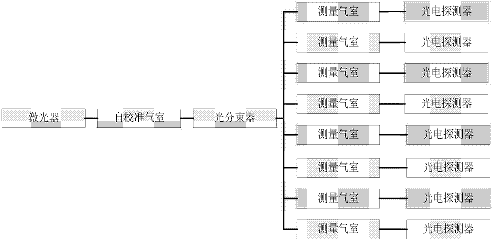
[0040] Such as figure 1 with figure 2 As shown, the distributed optical fiber methane sensing system of this embodiment includes a laser for emitting laser, a self-calibrating gas chamber, an optical beam splitter, and a measurement channel that are sequentially connected along the laser optical path, and at least two measurement channels are arranged in parallel. Each measurement channel includes a measurement gas chamber and a photodetector. The laser beam enters the photodetector after passing the measurement gas chamber; the self-calibration gas chamber includes potting box 1 and potting A housing 2, an optical fiber collimator I3 and an optical fiber collimator II4 are fixed in the potting box 1. The housing 2 is provided with a gas accommodating cavity 2a for accommodating self-calibration gas, and its left and right sides are symmetrically provided with fixing Base Ⅰ21 and holder Ⅱ22, fiber collimator Ⅰ3 fixed in holder Ⅰ21 and fiber collimator Ⅱ4 fixed in holder Ⅱ22 ar...


PUM


Abstract

The invention discloses a self-calibration gas chamber which comprises an encapsulation box and a shell, a first optical collimator and a second optical collimator which are encapsulated and fixed in the encapsulation box. The shell is provided with a gas holding chamber used for holding self-calibration gas and a first fixing seat and a second fixing seat which are symmetrically arranged on two sides of the gas holding chamber, and the first optical collimator fixed on the first fixing seat and the second optical collimator fixed on the second fixing seat are aligned with each other; first tail fiber of the first optical collimator and second tail fiber of the second optical collimator are respectively led out from optical fiber exits in two sides of the encapsulation box. The self-calibration gas chamber is simple in structure, easy to manufacture, simple in optical path adjusting manner and high in leakage, and high measurement precision is guaranteed; meanwhile, the invention further discloses a distributed optical fiber methane sensing system applying the self-calibration gas chamber.

Description

Technical field [0001] The invention relates to the technical field of coal mine gas monitoring, in particular to a self-calibrated gas chamber and a distributed optical fiber methane sensing system. Background technique [0002] At this stage, safety issues are an important issue that plagues coal production. Among them, gas disasters are the primary disaster in coal mines, accounting for more than 70% of the total number of major coal mine accidents nationwide. Gas monitoring has always occupied a prominent position in the underground coal mine monitoring and monitoring system. Existing gas monitoring technology, carrier catalytic principle methane sensor has problems such as insufficient measurement accuracy, short adjustment period, narrow measurement range, and susceptibility to environmental gas interference; infrared methane sensor based on "Non-dispersive Infrared Detection" (NDIR) technology , Which overcomes most of the problems, but there are also problems such as bei...

Claims


Application Information

Patent Timeline
Patent Type & Authority Applications(China)
IPC IPC(8): G01N21/39
CPCG01N21/39
Inventor 郭清华李军谭凯张书林龚仲强王尧逯彪郑芳菲蒋波彭迈
Owner CHINA COAL TECH & ENG GRP CHONGQING RES INST CO LTD
Why Eureka
Try Eureka