Drawer biofilter adopting composite slow release carbon source as filler

A biological filter, slow-release carbon source technology, applied in biological water/sewage treatment, granular microbial carrier treatment, multi-stage water treatment, etc., can solve problems such as affecting denitrification effect, increasing operating cost, and showing acidity of solution. , to achieve good treatment effect, low operating cost, and the effect of reducing acidity

Inactive Publication Date: 2017-10-20
UNIV OF SHANGHAI FOR SCI & TECH +1
View PDF7 Cites 6 Cited by
  • Summary
  • Abstract
  • Description
  • Claims
  • Application Information

AI Technical Summary

Problems solved by technology

[0003] This kind of solid organic carbon source that can continuously release carbon sources will gradually release less carbon during the operation of the device, which will eventually lead to the failure of the filler; the solution after soaking is acidic, which affects the denitrification effect
Moreover, the replacement of fillers in traditional biofilters will cost a lot of manpower and material resources, and it is troublesome and inconvenient, which increases operating costs.

Method used


Image

  • Drawer biofilter adopting composite slow release carbon source as filler

Examples


Embodiment 1

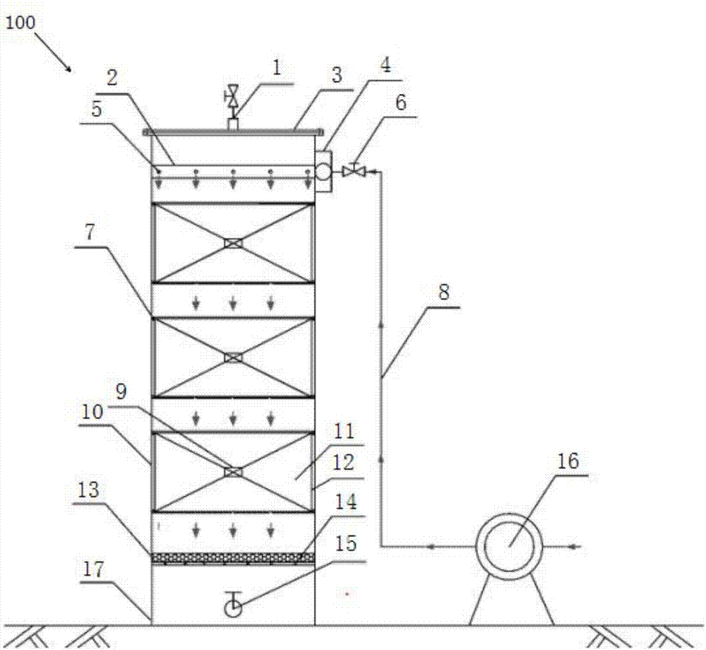
[0018] figure 1 It is a schematic diagram of the overall structure in an embodiment of the present invention.

[0019] Such as figure 1 As shown, a drawer-type biofilter 100 filled with a composite slow-release carbon source in this embodiment includes: an exhaust port 1, a water distribution unit, a drawer unit, a supporting layer, a water outlet 15 and a housing 17 .

[0020] The water distribution unit is used to distribute the water to be treated to the drawer unit.

[0021] The water distribution unit includes: a peristaltic pump 16, which is arranged outside the casing 17, and is used to control the flow rate of the water to be treated; a water inlet conduit 8, which is connected to the peristaltic pump 16, and is used to allow the water to be treated to enter; the water inlet valve 6 is set On the water inlet conduit 8; the shunt pipe 4 is arranged on the top side wall of the housing 17 for shunting the water to be treated; there are multiple water distribution condu...

Embodiment 2

[0038] In the second embodiment, the same structures as those in the first embodiment are given the same symbols, and the same descriptions are omitted.

[0039]Using the same device as in Example 1, the experimental raw water is artificial water distribution, simulating the water quality of the secondary effluent of the urban sewage plant, the effluent water quality is 45-55 mg / l for COD, 6.6-7.4 for pH, DO, NH 3 -N, NO 3 - The mass concentrations of -N and TN are 5.0-7.8, 0.8-1.4, 12.5-14.5, 13.7-17.1 mg / l, respectively. The flow rate is set to 0.02L / min, two drawer units are used, the hydraulic retention time is 24min, and other conditions are the same as in the first embodiment. The experiment adopts intermittent water feeding method.

Embodiment 3

[0041] In the third embodiment, the same structures as those in the first embodiment are assigned the same symbols, and the same descriptions are omitted.

[0042] Using the same device as in Example 1, the raw water is taken to the secondary effluent of an urban sewage plant, and the effluent quality is 50-60 mg / l for COD, 6.5-7.5 for pH, DO, NH 3 -N, NO 3 - The mass concentrations of -N and TN are 5.2-7.5, 0.5-1.5, 12.8-15.8, 13.7-17.7 mg / l, respectively. The flow rate is set to 0.02L / min, three drawer units are used, the hydraulic retention time is 36min, and other conditions are the same as in the first embodiment. The experiment adopts intermittent water feeding method.


PUM

PropertyMeasurementUnit
diameteraaaaaaaaaa
particle size (mesh)aaaaaaaaaa
particle diameteraaaaaaaaaa

Abstract

The invention discloses a drawer biofilter adopting a composite slow release carbon source as a filler. The drawer biofilter comprises a shell, a gas discharging opening, a water distribution unit, drawer units, a supporting layer and a water outlet, wherein the water distribution layer is used for distributing water to be treated to the drawer units, the drawer units are used for filtering the water to be treated, every drawer unit comprises a drawer and the composite slow release carbon filler contained in the drawer, the supporting layer comprises sand grains and a supporting plate and is arranged below the drawer units, the water outlet is arranged in the bottom of the shell and is used for discharging ammonia nitrogen adsorption treated water, the gas discharging opening is arranged at the top of the shell, is connected with the shell through a flange, and is used for discharging N2 in the reaction process. The composite slow release filler is obtained through blending and wrapping of a viscose material used as the supporting layer and agricultural wastes and adsorptive alkaline substances used as an adsorption layer, the integral body of the filler is cylindrical, granular or spherical in shape, the diameter is 3-6 mm, and the porosity is 50-60%.

Description

technical field [0001] The invention belongs to the field of environmental engineering sewage treatment, and in particular relates to a drawer-type biological filter tank with composite slow-release carbon source as filler. Background technique [0002] Denitrification biological filter has the characteristics of large hydraulic load, large biomass, low investment and high treatment efficiency. It is currently the key technology for deep denitrification treatment of urban sewage with low carbon-to-nitrogen ratio. Traditional biological denitrification is carried out by adding liquid carbon sources such as methanol and glucose for denitrification, which can easily lead to insufficient or excessive carbon source addition, which not only increases the cost of denitrification, but also complicates the operation of the system and the problem of secondary pollution is more prominent. The use of new solid carbon sources has become one of the research hotspots in denitrification and...

Claims


Application Information

Patent Timeline
Patent Type & Authority Applications(China)
IPC IPC(8): C02F3/30
CPCC02F3/301C02F3/302C02F2003/001C02F2003/003C02F2301/08
Inventor 刘洪波管祥雄薛璐璐符策竿陈子华姚洋洋熊亚波宋筱关永年肖健陈勇
Owner UNIV OF SHANGHAI FOR SCI & TECH
Why Eureka
Try Eureka