
Flexible stress sensor and preparation method thereof

A stress sensor and flexible technology, applied in the field of sensors, can solve the problems of low sensitivity, harsh spinning conditions, unfavorable integration, etc., and achieve the effects of improving detection resolution and sensitivity, easy preparation conditions, and avoiding circuit manufacturing processes

Inactive Publication Date: 2017-10-20
WUYI UNIV
View PDF5 Cites 25 Cited by
  • Summary
  • Abstract
  • Description
  • Claims
  • Application Information

AI Technical Summary

Problems solved by technology

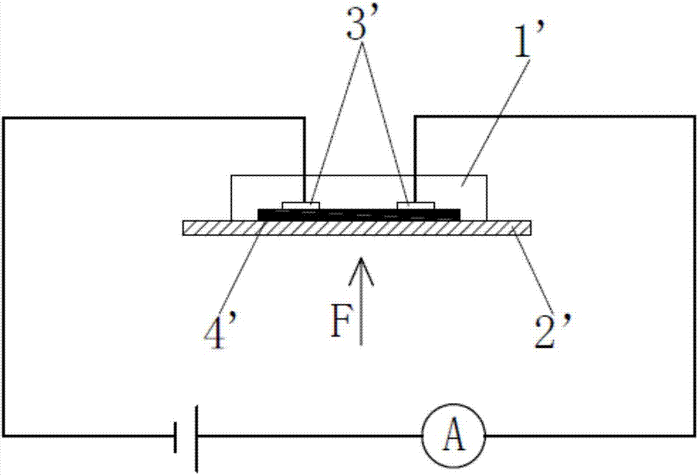
[0006] (1) Using a whole piece of nanostructured fiber membrane as a resistance strain gauge leads to a relatively large sensor size, which is difficult to apply in miniaturized equipment, and is also not conducive to the detection of small pressures, and the resistance change rate of the sensor does not exceed 0.2%. , the current change in the connected test circuit is only a few tenths of a microampere, and there are problems of insufficient test resolution and low sensitivity;
[0007] (2) The electrodes need to be arranged symmetrically at both ends of the nanostructured fiber membrane, so as to ensure that the whole fiber membrane can sense the pressure uniformly. Integrating multiple sensors into an array and making the individual sensors independent and insulated from each other requires the design of complex circuits and difficult circuit manufacturing processes, which may reduce the overall flexibility and practicability of the sensor array;
[0008] (3) The preparation steps are complicated. First, the PVDF spinning solution must be prepared, and then the PVDF fiber membrane is prepared with a spinning voltage of 10 to 14 kilovolts, and then the polyaniline reaction solution is prepared, and the PVDF fiber membrane is soaked in the polyaniline reaction solution. Then take it out and dry it to get the nanostructured polyaniline coaxial fiber membrane, and finally install the electrode and PDMS film to complete the assembly of the sensor. The whole preparation process uses a lot of reagents, many steps, many equipments, and harsh spinning conditions. , so the cost of this sensor is high
[0009] Therefore, the current technical development of flexible stress sensors is not yet mature, and there is still much room for improvement.

Method used


Image

  • Flexible stress sensor and preparation method thereof
  • Flexible stress sensor and preparation method thereof
  • Flexible stress sensor and preparation method thereof

Examples


Embodiment 1

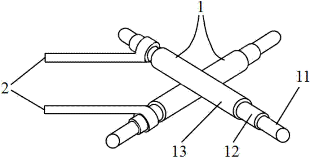
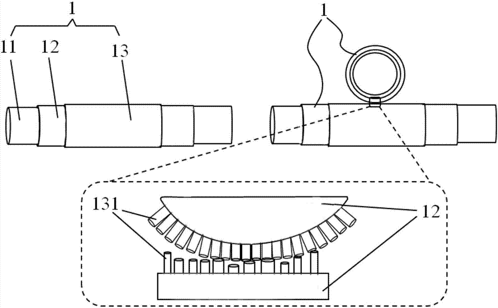
[0046] Please also see figure 2 with image 3 , the flexible stress sensor provided by this embodiment includes two sensing components 1, each sensing component 1 includes a flexible fiber filament 11 and a nanostructure film 13 covering the flexible fiber filament 11, and the flexible fiber filament 11 is a carbon fiber filament , the nanostructure film 13 is a tungsten oxide nanowire film. Each sensing component 1 is connected with a wire 2 extending outward, and the wire 2 is connected with the flexible fiber filament 11 . The two sensing components 1 are cross-stacked, and the nanostructure thin films 13 of the two sensing components 1 are in contact with each other at the intersection.

[0047] The flexible fiber filament 11 in this embodiment is a conductive carbon fiber filament, so no additional conductive layer 12 is provided on its surface.

[0048] The preparation method of the flexible stress sensor specifically includes the following steps:

[0049] S11: In a...

Embodiment 2

[0055] Please also see figure 2 with image 3 , the structure of the flexible stress sensor provided by this embodiment is basically the same as that of Embodiment 1, the difference is that: the surface of the flexible fiber filament 11 is provided with a conductive layer 12, and each sensing component 1 is connected with an outwardly extending The wire 2 is connected, and the wire 2 is connected to the conductive layer 12 of the flexible fiber filament 11 .

[0056] The preparation method of the flexible stress sensor comprises the following steps:

[0057] S00: Prepare a conductive layer 12 on the surface of the flexible fiber 11 by thermal evaporation coating method or magnetron sputtering method.

[0058] S10: Prepare a layer of nanostructure thin film 13 on the surface of the conductive layer 12 of the flexible fiber filament 11 by thermal evaporation coating method, and manufacture the sensing component 1 .

[0059] S20: Lay the two sensing components 1 up and down s...

experiment example

[0061] Such as Image 6 As shown, the flexible stress sensor of embodiment 1 is connected to the test circuit, Image 6 U represents the voltage of the power supply, R s Represents the resistance of the flexible stress sensor, and R represents a resistor connected in series with the flexible stress sensor. Such as Figure 7 As shown, an external force F is applied to the intersection of the two sensing components in the flexible stress sensor during the test, and a multimeter is used to monitor the voltage across the series resistor R in real time.

[0062] Please refer to Figure 8 , which is a performance test result diagram of the flexible stress sensor of the present invention, the ordinate in the figure is the voltage value at both ends of the series resistance R, when the external force F is applied to the flexible stress sensor, R s The resistance changes accordingly, which in turn changes the current in the circuit, and finally manifests as a change in the voltage ...


PUM

PropertyMeasurementUnit
lengthaaaaaaaaaa
diameteraaaaaaaaaa

Abstract

The present invention relates to a flexible stress sensor. The flexible stress sensor comprises two sensing assemblies; each sensing assembly includes a flexible fiber wire and a nanostructured film coating the flexible fiber wire; the flexible fiber wire is made of a conductive material or the surface of the flexible fiber wire is provided with a conductive layer; the nanostructured film is made of a conductive material or a semiconductor material; the two sensing assemblies are cross-stacked; and the nanostructured films of the two sensing assemblies contact with each other at the intersection of the two sensing assemblies. The present invention also relates to a preparation method of the flexible stress sensor. The flexible stress sensor of the invention has the advantages of small size, high resolution, high sensitivity and simple preparation, is suitable for being applied to miniaturized and integrated equipment and can be used for making wearable equipment for detecting human health.

Description

technical field [0001] The invention relates to the technical field of sensors, in particular to a flexible stress sensor and a preparation method thereof. Background technique [0002] With the advent of the era of wearable electronic products, wearable devices for real-time monitoring of human health status have attracted more and more attention. In wearable devices, the most critical flexible stress sensor related technologies are often mastered in industrially developed countries such as the United States, Japan, and Germany. [0003] In order to break the technical monopoly of foreign countries on high-performance flexible stress sensors, domestic researchers have continuously proposed innovative technologies related to this field, especially using tiny micro-nano structures as sensing materials to improve the sensitivity of flexible stress sensors. At present, some domestic enterprises have been able to produce flexible stress sensors with high sensitivity, but despit...

Claims


Application Information

Patent Timeline
Patent Type & Authority Applications(China)
IPC IPC(8): G01L1/22B82Y30/00B82Y35/00B82Y15/00
CPCB82Y15/00B82Y30/00B82Y35/00G01L1/22
Inventor 罗坚义黄景诚黄辉唐秀凤许友鑫李远兴
Owner WUYI UNIV
Learn More