Cascade microsphere resonant cavity type humidity sensor

A microsphere resonant cavity, humidity sensor technology, applied in transmittance measurement and other directions, can solve the problems of reducing sensor stability and service life, affecting sensing performance, polymer aging, etc., achieving small size, high sensitivity, and stability. Good results

Inactive Publication Date: 2017-10-20
NORTHWEST UNIV
View PDF5 Cites 6 Cited by
  • Summary
  • Abstract
  • Description
  • Claims
  • Application Information

AI Technical Summary

Problems solved by technology

[0006] The above-mentioned optical fiber light transmission type and optical fiber sensing humidity sensors are usually based on changes in the external refractive index to achieve sensing. In addition to humidity, changes in temperature and gas concentration will also cause changes in the refractive index, thereby introducing cross-se

Method used


Image

  • Cascade microsphere resonant cavity type humidity sensor
  • Cascade microsphere resonant cavity type humidity sensor
  • Cascade microsphere resonant cavity type humidity sensor

Examples


Example Embodiment

[0025] Example 1

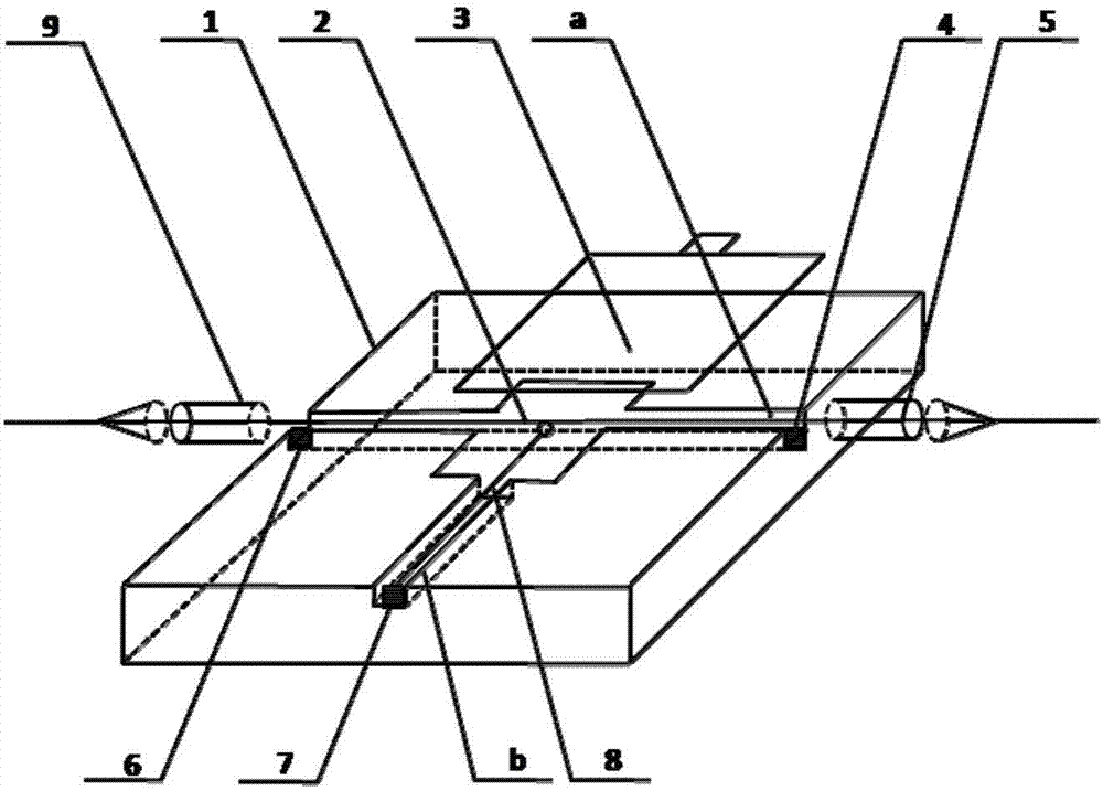
[0026] exist figure 1 Among them, the cascaded microsphere resonant cavity type humidity sensor of the present invention includes a sensor substrate 1. The sensor substrate 1 of this embodiment is made of acrylic glass, and the sensor substrate 1 is provided with horizontal installation grooves a and vertical installation grooves perpendicular to each other. b, in the horizontal installation slot a, the taper fiber 2 is fixedly installed with the taper fiber left adjustment screw 4 and the taper fiber right adjustment screw 7. The taper fiber 2 in this embodiment is pulled by a commercial 1550 optical fiber with a diameter of 125um. Made by cone method, the diameter of the cone area is 1um, the evanescent field in the fusion cone fiber 2 is more likely to be coupled, and the sensor sensitivity is improved. The left adjustment screw 4 of the fusion cone fiber and the right adjustment screw 7 of the fusion cone fiber can be adjusted and controlled. The height...

Example Embodiment

[0027] Example 2

[0028] In the above-mentioned embodiment 1, the fusion-tapered optical fiber 2 of the present embodiment is made by a commercial 1550 optical fiber with a diameter of 125um using the method of flame tapering, and the diameter of the cone area is 0.5um. The connection relationship and implementation of the remaining parts and parts Example 1 is exactly the same.

Example Embodiment

[0029] Example 3

[0030] In the above-mentioned embodiment 1, the fusion-tapered optical fiber 2 of the present embodiment is made of a commercial 1550 optical fiber with a diameter of 125um by means of flame tapering, and the diameter of the cone area is 3um. 1 is exactly the same.


PUM

PropertyMeasurementUnit
Diameteraaaaaaaaaa
Diameteraaaaaaaaaa
Diameteraaaaaaaaaa

Abstract

The invention discloses a cascade microsphere resonant cavity type humidity sensor. The sensor comprises a sensor base, wherein a transverse mounting groove a and a longitudinal mounting groove b which are perpendicular to each other are formed in the sensor base; a fused optic fiber is arranged in the transverse mounting groove a through a fused optic fiber leftward adjusting screw and a fused optic fiber rightward adjusting screw; a left optic fiber wire jumper protection sleeve and a right optic fiber wire jumper protection sleeve are respectively arranged at the left and right ends of the fused optic fiber; a single-mode optic fiber is arranged in the longitudinal mounting groove b through a single-mode optic fiber adjusting screw; and the single-mode optic fiber is arranged relative to the a tapered zone of the fused optic fiber. The sensor is wide in humidity response range and high in sensitivity coefficient, and compared with the traditional humidity sensor, the sensor has the advantages of small size, wide response range, high sensitivity and high stability, and can be applied to the fields of aerospace, meteorology, clinical medicine and civil engineering.

Description

technical field [0001] The invention belongs to the technical field of optical fiber sensors, and in particular relates to a cascaded microsphere resonant cavity type humidity sensor. Background technique [0002] Humidity is an important physical quantity. Accurate measurement of humidity is required in many fields such as aerospace, meteorology, agriculture, food industry, clinical medicine, manufacturing, and civil engineering. There are three main types of traditional humidity sensors: electrolyte humidity sensors, semiconductor ceramic humidity sensors and organic polymer humidity sensors. [0003] Compared with the traditional humidity sensor, the optical fiber humidity sensor has been widely used in various occasions due to its small size, light weight, strong anti-electromagnetic interference ability, corrosion resistance, simple production, high precision, easy integration and high resolution. Humidity measurement in progress. Since the emergence of optical fiber ...

Claims


Application Information

Patent Timeline
IPC IPC(8): G01N21/59
CPCG01N21/59
Inventor 荣强周梁磊乔学光忽满利
Owner NORTHWEST UNIV
Why Eureka
Try Eureka