A method of inductive load current detection

An inductive load, current detection technology, applied in the direction of measuring current/voltage, measuring device, measuring electrical variables, etc., can solve problems such as difficult design, achieve good real-time performance and measurement accuracy, easy to implement, and simple steps.

Active Publication Date: 2020-01-07
SHAANXI FAST GEAR CO
View PDF6 Cites 0 Cited by
  • Summary
  • Abstract
  • Description
  • Claims
  • Application Information

AI Technical Summary

Problems solved by technology

The advantage of the Hall sensor is that it can measure large currents remotely without loss, but the disadvantage is that it is easily affected by environmental noise and is not easy to design

Method used


Image

  • A method of inductive load current detection
  • A method of inductive load current detection
  • A method of inductive load current detection

Examples


Embodiment Construction

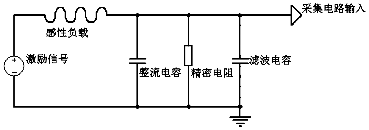
[0030] The invention discloses an inductive load current detection method. By using a rectifier circuit composed of precision resistors and capacitors and matching certain filtering processing, the actual current value after the superimposition of the original current passing through the inductive load and the induced current can be objective and comprehensive. The insinuation into a voltage value is convenient for the analog acquisition unit of the MCU to perform signal processing.

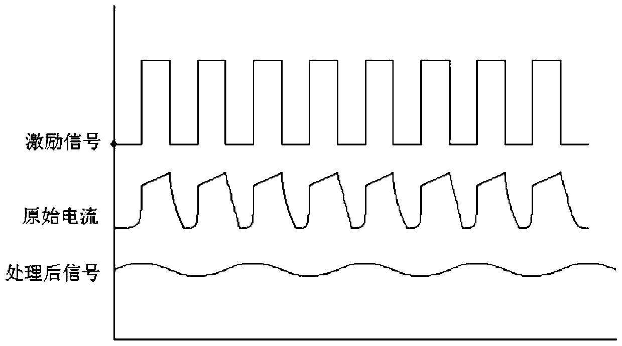
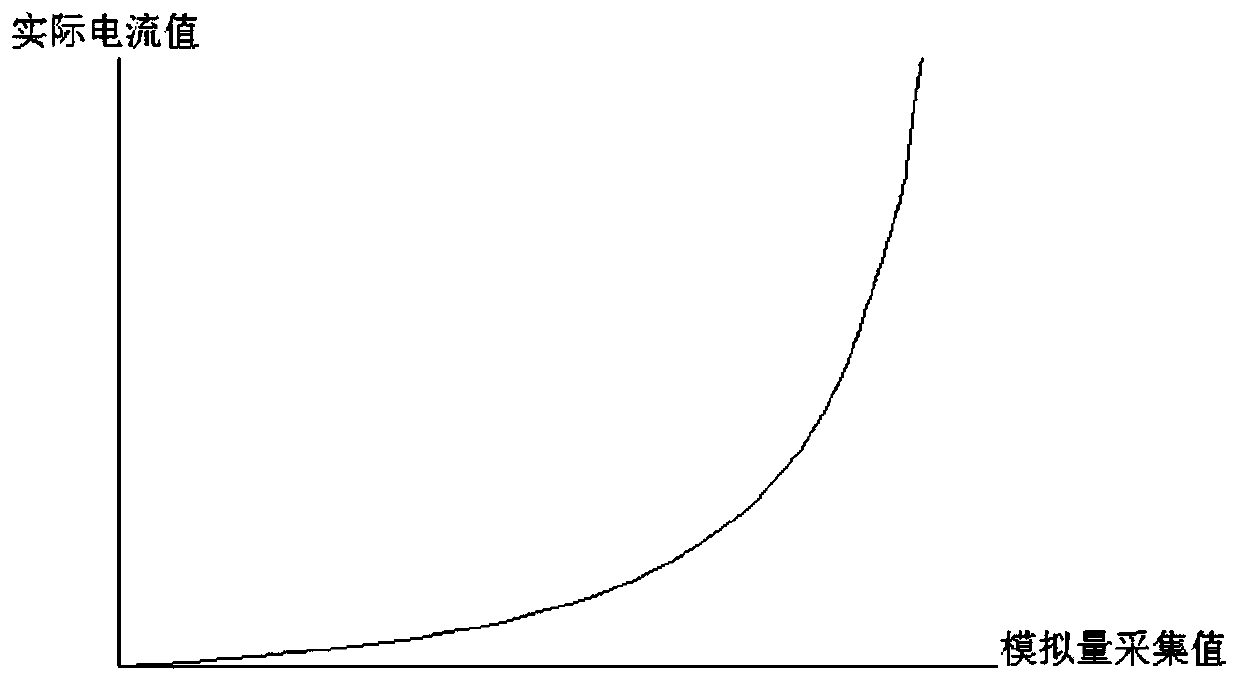
[0031] The rectified analog signal has a certain collection value, but due to the influence of the inductive load's own induced electromotive force when the frequency conversion AC signal is applied, the signal fluctuates. Moreover, since the signal is a conversion process of the original current, its signal quantity cannot be linearly corresponded to the actual current value. The signal captured by the MCU first needs to be filtered to filter out false values ​​in the analog signal. Then, the i...


PUM


Abstract

The invention discloses an inductive load current detecting method which comprises the steps of establishing a rectifier circuit by means of a precise reactor and a capacitor, adding a filtering capacitor for performing filtering processing; then inputting an excitation signal into an inductive load, connecting the inductive load with a microcontrol unit (MCU) through the rectifier circuit; optimizing a signal filtering processing algorithm to a standard function by the microcontrol unit (MCU), performing calibration for obtaining an inductive load current value; and finally implanting the circuit into an existing circuit for performing current detection. The inductive load current detecting method has advantages of simple process, easy realization, effective processing for different inductive loads, relatively high hardware transplantability, and relatively low hardware circuit size. The hardware circuit can be easily embedded into an original control circuit board as an integral unit for performing current detection. Furthermore the current value processed by the method has high real-time performance and high measurement precision and can be used for fine load controlling or fault diagnosis. Particularly the inductive load current detecting method has high practical value in execution mechanisms such as electromagnetic valve, thereby remarkably improving control precision of the execution mechanism.

Description

【Technical field】 [0001] The invention belongs to the technical field of current detection, and in particular relates to an inductive load current detection method. 【Background technique】 [0002] There are many sampling components that can be used to measure load current, but no single component can cover all applications. Each sampling element has its advantages and disadvantages. For example, the power dissipation of the shunt resistor will lead to a decrease in system efficiency, and the voltage drop generated by the current flowing through the shunt resistor is too large to be suitable for low output voltage applications. The advantage of the DCR (inductor DC resistance) current detection circuit is that it can measure the current in the switching power supply without loss, but the sampling accuracy of the DCR sampling circuit depends on the matching accuracy of the peripheral parameters (R, C) and the inductor. The advantage of the Hall sensor is that it can measure ...

Claims


Application Information

Patent Timeline
Patent Type & Authority Patents(China)
IPC IPC(8): G01R19/00
CPCG01R19/00
Inventor 李睿
Owner SHAANXI FAST GEAR CO
Why Eureka
Try Eureka