Terahertz image frequency suppression frequency mixing circuit

A technology of mixing circuit and terahertz mirror, which is applied in the field of terahertz waves, achieves the effects of high compression point, improved overall performance, and improved noise figure

Active Publication Date: 2017-10-20
四川久成泰安科技有限公司
View PDF6 Cites 10 Cited by
  • Summary
  • Abstract
  • Description
  • Claims
  • Application Information

AI Technical Summary

Problems solved by technology

[0005] The technical problem to be solved by the present invention is to suppress the image frequency in the terahertz frequency band, and the purpose is to provide a terahertz image frequency suppression mixing circuit, which realizes the suppr...

Method used


Image

  • Terahertz image frequency suppression frequency mixing circuit
  • Terahertz image frequency suppression frequency mixing circuit
  • Terahertz image frequency suppression frequency mixing circuit

Examples


Embodiment 1

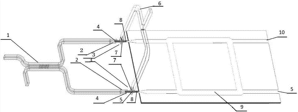
[0039] Such as Figure 1-9 As shown, the present invention includes a terahertz image frequency suppression mixing circuit, including a radio frequency 3dB branch waveguide directional coupler 1, a terahertz fundamental wave mixer 3, a local oscillator H-plane waveguide power divider 6 and an intermediate frequency branch line coupling 9, the radio frequency 3dB branch waveguide directional coupler 1 divides the incoming radio frequency signal into two paths of mutually orthogonal signals, and couples them to two terahertz fundamental wave mixers 3 through waveguides; the local oscillator H-plane waveguide The power divider 6 couples the local oscillator drive signal waveguide to the two terahertz fundamental wave mixers 3, and the intermediate frequency signals generated in the two terahertz fundamental wave mixers 3 enter the intermediate frequency branch line coupler 9 and are separated The high sideband IF output 5 and the low sideband IF output 10.

[0040] In various ap...

Embodiment 2

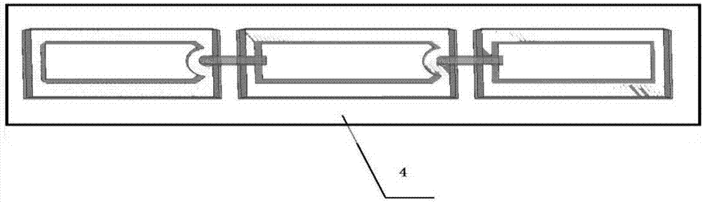
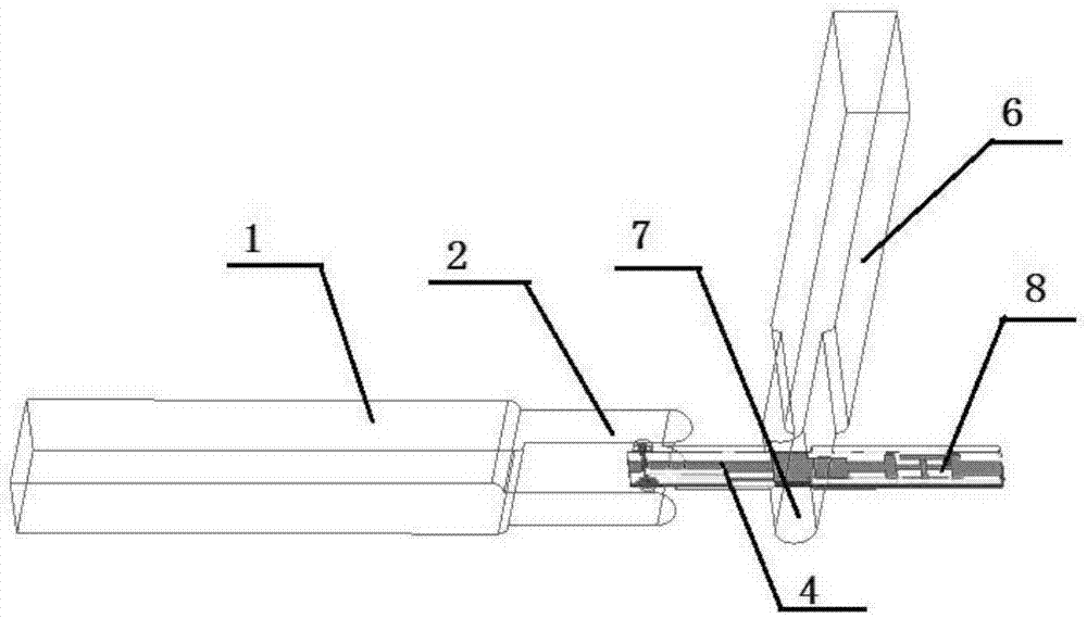
[0045] Such as image 3 As shown, this embodiment is preferably as follows on the basis of Embodiment 1: Terahertz fundamental wave mixer 3 includes radio frequency waveguide-microstrip line 2, Schottky diode 4, local oscillator waveguide-microstrip line 7 and intermediate frequency filter 8, the two output ports of the radio frequency 3dB branch waveguide directional coupler 1 are connected to the radio frequency waveguide-microstrip line 2, and the two output ports of the local oscillator H-plane waveguide power divider 6 are connected to the local oscillator waveguide-microstrip Line 7, RF waveguide-microstrip line 2 and local oscillator waveguide-microstrip line 7 are all connected to Schottky diode 4, and the intermediate frequency signal generated by mixing is output through intermediate frequency filter 8, and the output terminal of intermediate frequency filter 8 is connected to intermediate frequency divider Branch coupler 9. Among them, the RF waveguide-microstrip l...

Embodiment 3

[0054] Such as Figure 7 As shown, this embodiment is preferably as follows on the basis of the above embodiments: the local oscillator H-plane waveguide power divider is a local oscillator H-plane Y-shaped waveguide power divider processed by 3D printing technology. In order to avoid the arrangement of multi-level circuits, the local oscillator H-plane waveguide power divider is processed in the vertical direction by using 3D printing technology. Using 3D printing technology to process the local oscillator H-plane waveguide power divider can not only greatly reduce the transmission loss caused by cutting off the wall current by traditional micromachining, but also reduce the insertion loss of the circuit, and can make the circuit from the traditional planar circuit to the new three-dimensional Circuit structure changes. This new three-dimensional circuit structure enables the intermediate frequency coupling ring circuit and the microstrip line structure of the mixer to be di...


PUM


Abstract

The invention discloses a terahertz image frequency suppression frequency mixing circuit comprising a radio frequency 3dB branch waveguide directional coupler, terahertz fundamental wave frequency mixers, a local oscillator H-plane waveguide power divider and an intermediate frequency branch line coupler. The radio frequency 3dB branch waveguide directional coupler equally divides the entered radio frequency signal into two paths of mutually orthogonal signals to be coupled to the two terahertz fundamental wave frequency mixers through the waveguide. The local oscillator H-plane waveguide power divider couples a local oscillator driving signal to the two terahertz fundamental wave frequency mixers through the waveguide, intermediate frequency signals generated in the two terahertz fundamental wave frequency mixers enter the intermediate frequency branch line coupler and then the separated high sideband intermediate frequency output and low sideband intermediate frequency output can be obtained. With application of the principle, the image frequency can be suppressed in the terahertz band, the receiver noise factor can be optimized, the image frequency can be prevented from interfering a terahertz receiver system to generate false correspondence and the error rate of the system can be reduced.

Description

technical field [0001] The invention relates to the field of terahertz waves, in particular to a terahertz image frequency suppression mixing circuit. Background technique [0002] Terahertz waves (Terahertz) refer to electromagnetic waves with a frequency band between 0.1 and 10 THz and a wavelength between 0.03 mm and 3 mm. It is not only the transition from electronics to optics, but also the transition from macro to micro theory, which shows that both electronic and optical theoretical methods can be tried. The special frequency band of terahertz makes it have many characteristics: such as high information capacity, high resolution, good spatial and temporal coherence, and spectral characteristic absorption. These unique characteristics inevitably make terahertz waves have great research value, and have great application prospects in many fields such as wireless communication, astronomy, radar remote sensing detection, security detection, and national defense and milita...

Claims


Application Information

Patent Timeline
IPC IPC(8): H03D7/16
CPCH03D7/161Y02D30/70
Inventor 杨晓艳李健柴劲松邵一慧陈宁波吴三统纪东峰牛中乾
Owner 四川久成泰安科技有限公司
Why Eureka
Try Eureka