High propylene yield catalytic conversion method

A catalytic conversion method, propylene technology, applied in catalytic cracking, chemical instruments and methods, cracking, etc., can solve the problems of high yield of dry gas and coke, small contribution of propylene yield, increase of coke and dry gas yield, etc. Achieve the effects of increasing propylene yield, reducing energy consumption, and reducing yield

Active Publication Date: 2017-10-24
QINGDAO JINGRUN PETROCHEM DESIGN INST CO LTD
View PDF5 Cites 16 Cited by
  • Summary
  • Abstract
  • Description
  • Claims
  • Application Information

AI Technical Summary

Problems solved by technology

Regardless of DCC or DCC-PLUS, a raw oil reactor is divided into two cracking reaction zones directly connected in series, that is, the riser and the fluidized bed both carry out catalytic cracking reaction, the riser part carries out the raw oil cracking reaction, and the fluidized bed part Make the intermediate products and catalysts in the riser reaction zone directly enter the fluidized bed reaction zone for secondary cracking reaction to increase the production of propylene, and the whole fraction of raw oil reaction products, including oil slurry, re-refined oil and diesel oil, all enter the fluidized bed reaction The secondary reaction in the fluidized bed continues in the fluidized bed, while oil slurry, re-refined oil, and diesel oil are rich in aromatics, which contribute little to the yield of propylene. Excessive reaction causes an increase in the yield of coke and dry gas; DCC and DCC-PLUS The catalyst in the fluidized bed reaction zone is a carbon-deposited catalyst after the reaction of raw oil, and the catalytic cracking performance of small molecular components is reduced. In order to increase the yield of propylene, it is often necessary to further increase the reaction temperature in the fluidized bed reaction zone, which will inevitably lead to catalytic cracking reaction. Restricted, the thermal reaction increases, reducing the selectivity of propylene, resulting in high yields of dry gas and coke; both fluidized bed DCC and DCC-PLUS use regenerant circulation, and the space velocity of the fluidized bed reaction zone for a fixed amount of raw material It can only be controlled by the amount of catalyst in the reactor. For this reason, the reaction part itself needs to be equipped with catalyst storage, stripping and catalyst level adjustment measures, which increases the complexity of the reactor; in addition, in the existing riser and fluidization In the bed series reactor, the bottom of the riser, that is, the pre-lift section, has the highest temperature in the entire reaction process, and the riser reaction zone is the high-temperature zone second only to the pre-lift section at the bottom of the riser; between the fluidized bed reaction zone and the gas-solid separator All are dilute phase spaces, and the oil and gas still carry a large amount of catalyst when leaving the fluidized bed, and the residence time of the oil and gas leaving the fluidized bed to the gas-solid separator is more than 20 seconds, resulting in the reaction not being terminated in time, further thermal cracking of propylene, and affecting product distribution and propylene selectivity
[0007] The existing double-riser technology is to separate different fractions through a fractionation tower, heat exchange and cool them into liquids, and then return to the reactor. It is still liquid) into the second reaction system for further conversion. After the process of cooling first and then heating up, the investment in equipment and energy consumption is increased, which greatly reduces the economical efficiency of the process technology.

Method used


Image

  • High propylene yield catalytic conversion method
  • High propylene yield catalytic conversion method
  • High propylene yield catalytic conversion method

Examples


Embodiment approach 1

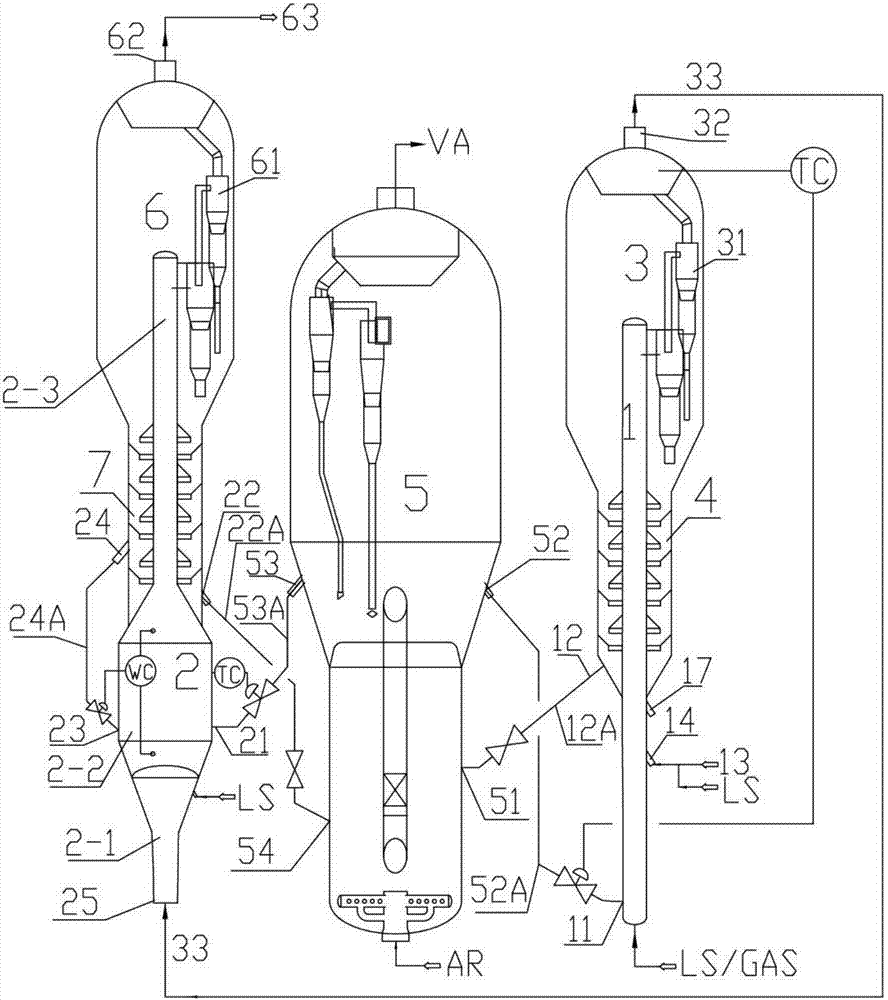
[0045] Such as figure 1 As shown, a catalyst regenerator and two reaction systems are set;

[0046] The raw oil is catalyzed in the first reaction system, and the reaction product, namely the first reaction oil gas 33, enters the second reaction system in gaseous state for further catalytic reaction; the two reaction systems use the same catalyst; the first reaction system is composed of the first The reactor 1, the first settler 3, and the first stripper 4 are composed; the second reaction system is composed of a separate second reactor 2, the second settler 6, and the second stripper 7;

[0047] After the fresh raw oil 13 is atomized by the steam LS, it enters the first reactor 1 through the raw oil inlet pipe 14, and is gasified after being in contact with the first reactor regeneration agent 52A sent through the first regeneration inclined pipe 11 and the regenerator 5 , and flow upward along the riser of the first reactor 1 to complete the reaction, and the first reactio...

Embodiment approach 2

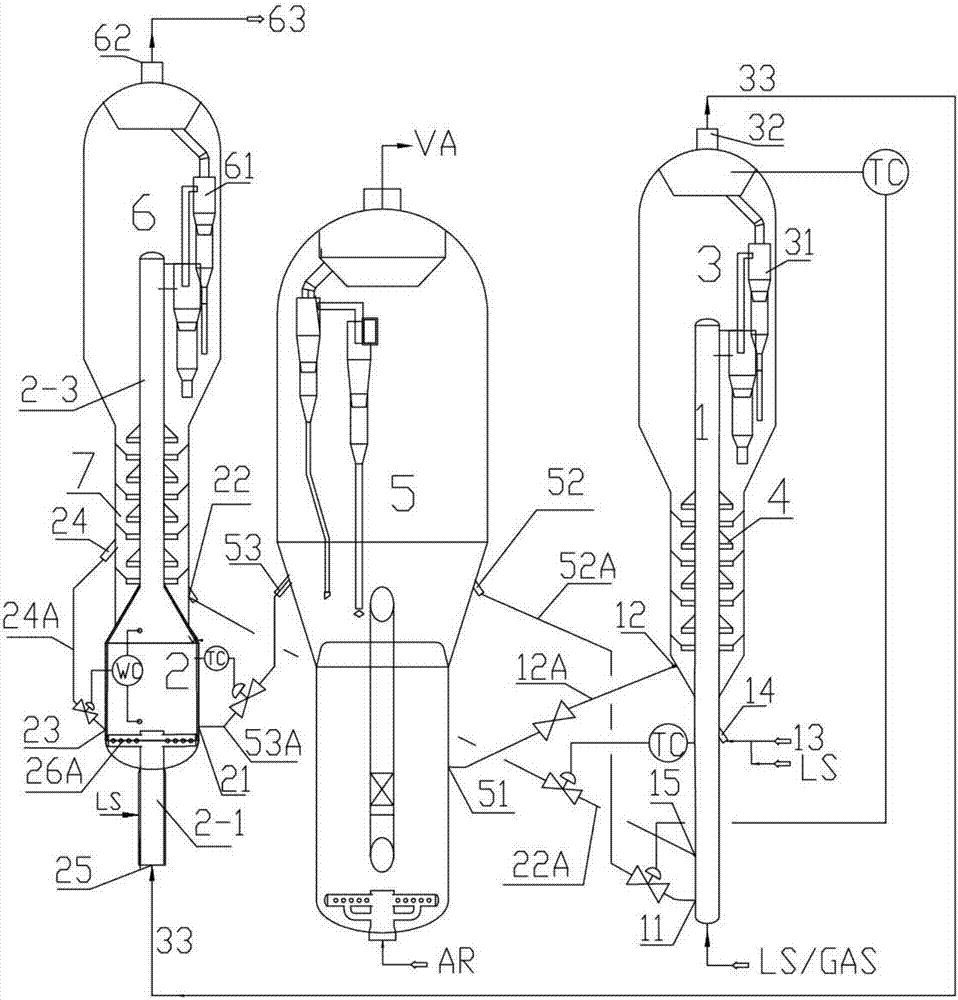
[0052] Such as figure 2 As shown, a catalyst regenerator and two reaction systems are set;

[0053] The raw oil is catalyzed in the first reaction system, and the reaction product, namely the first reaction oil gas 33, enters the second reaction system in gaseous state for further catalytic reaction; the two reaction systems use the same catalyst;

[0054] After the fresh raw oil 13 is atomized by the steam LS, it enters the first reactor 1 through the raw oil inlet pipe 14, and is gasified after being in contact with the first reactor regeneration agent 52A sent through the first regeneration inclined pipe 11 and the regenerator 5 , and react upwards along the riser of the first reactor 1; part of the second reactor’s standby agent 22A is drawn from the second standby standpipe 22, enters the first reactor 1, and flows upwardly with the first reactor The regeneration agent 52A is mixed and continues to be used in the reaction of the raw material oil, and the reaction temper...

Embodiment approach 3

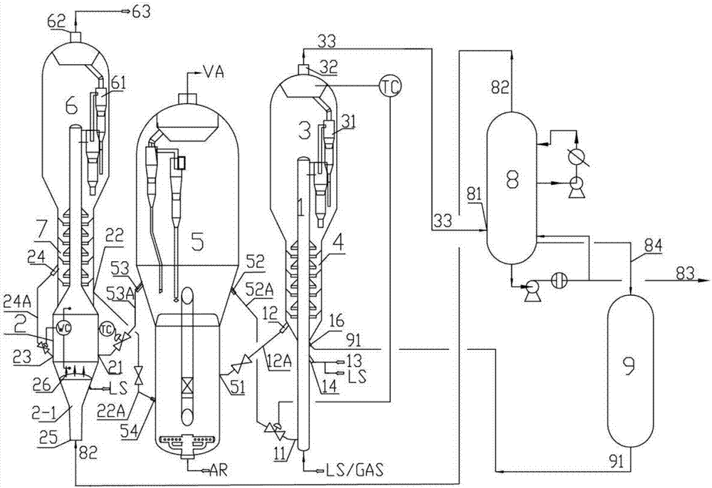
[0057] Such as image 3 As shown, a catalyst regenerator and two reaction systems are set;

[0058] The raw oil is catalyzed in the first reaction system, and the reaction product, namely the first reaction oil gas 33, enters the second reaction system in gaseous state for further catalytic reaction; the two reaction systems use the same catalyst; the first reaction system is composed of the first The reactor 1, the first settler 3, and the first stripper 4 are composed; the second reaction system is composed of a separate second reactor 2, the second settler 6, and the second stripper 7;

[0059] After the fresh raw oil 13 is atomized by the steam LS, it enters the first reactor 1 through the raw oil inlet pipe 14, and is gasified after being in contact with the first reactor regeneration agent 52A sent through the first regeneration inclined pipe 11 and the regenerator 5 , and flow upward along the riser of the first reactor 1 to complete the reaction, and the first reactio...


PUM


Abstract

The invention belongs to the technical field of petroleum hydrocarbon catalytic conversion, and especially relates to a high propylene yield catalytic conversion method. According to the method, a catalyst regenerator and two reaction systems are arranged, raw oil (13) carries out catalytic reactions in the first reaction system, all reaction products (or part of the reaction products) enter the second reaction system in a gas form and carry out catalytic reactions; a second reactor catalyst (22A) to be regenerated and a catalyst from the catalyst regenerator enter the second reactor (2); the fluidized catalytic cracking reaction of first reactive oil gas (33) is realized again, two reaction systems use a same catalyst, and the reaction products are separated in individual precipitators to realize gas-solid separation and then discharged from the precipitators. The energy consumption is reduced, individual high temperature cracking reaction is realized, fluidized bed reaction is stopped rapidly, the contradiction between propylene increasing and dry gas reducing is solved, the propylene yield is increased, and at the same time, the yield of dry gas and coke is prominently reduced.

Description

technical field [0001] The invention belongs to the technical field of catalytic conversion of petroleum hydrocarbons, in particular to a catalytic conversion method capable of increasing the yield of propylene and producing more propylene. Background technique [0002] Propylene is one of the most important petrochemical raw materials. 70% of the propylene is produced from petroleum hydrocarbons by the tube furnace cracking method, and the other 30% of the propylene is provided by the catalytic cracking process. Drawing on the operation and design experience of the conventional heavy oil catalytic cracking reaction-regeneration system, researchers at home and abroad have developed a series of technologies for the production of propylene by catalytic cracking of heavy oil. [0003] KBR and Mobil Technology jointly developed the Maxofin technology for the production of propylene from heavy oil. The technology adopts a double-riser reactor. The conventional FCC raw material ...

Claims


Application Information

Patent Timeline
Patent Type & Authority Applications(China)
IPC IPC(8): C10G11/18B01J8/26
CPCB01J8/26B01J2219/00452B01J2219/2475C10G11/18C10G2300/4012C10G2300/4081C10G2300/708C10G2400/02C10G2400/20C10G2400/22
Inventor 石宝珍
Owner QINGDAO JINGRUN PETROCHEM DESIGN INST CO LTD
Why Eureka
Try Eureka