Electrofluid spray printing online detection and analysis control method
A control method and electro-fluid technology, applied in printing, printing devices, etc., can solve problems such as uncontrollability and disorder, and achieve the effect of improving precision, improving efficiency, and realizing manufacturing and forming.
- Summary
- Abstract
- Description
- Claims
- Application Information
AI Technical Summary
Problems solved by technology
Method used
Image


Examples
Embodiment 1
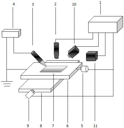
[0018] Example 1 , see figure 1 As shown, in the process of online detection and control analysis of electrofluid jet printing, the setting of the inspection error is first carried out. The present invention writes lines and patterns during the movement process, so it is necessary to calculate the error generated during the movement of the lines . In the error measurement of the present invention, the laser displacement sensor 10 is used to measure the shape error of the measured position point platform of the nanofiber 7, and the up and down variation of its position is determined as the systematic error of measurement. Upload the system error to the control computer as the error basis for measurement. The platform motion error is measured by the laser interferometer 11 as the system error of the platform motion.
[0019] The present invention adopts a laser displacement sensor, which is Keyence LK-G30, and installs the laser displacement sensor on the moving platform. ...
Embodiment 2
[0046] Example 2 , see figure 1 As shown, in the process of online detection and control analysis of electrofluid jet printing, the setting of the inspection error is first carried out. The present invention writes lines and patterns during the movement process, so it is necessary to calculate the error generated during the movement of the lines . In the error measurement of the present invention, the laser displacement sensor 10 is used to measure the shape error of the measured position point platform of the nanofiber 7, and the up and down variation of its position is determined as the systematic error of measurement. Upload the system error to the control computer as the error basis for measurement. The platform motion error is measured by the laser interferometer 11 as the system error of the platform motion.
[0047] The present invention adopts a laser displacement sensor, which is Keyence LK-G30, and installs the laser displacement sensor on the moving platform. ...
Embodiment 3
[0071] Example 3 , see figure 1 As shown, in the process of online detection and control analysis of electrofluid jet printing, the setting of the inspection error is first carried out. The present invention writes lines and patterns during the movement process, so it is necessary to calculate the error generated during the movement of the lines . In the error measurement of the present invention, the laser displacement sensor 10 is used to measure the shape error of the measured position point platform of the nanofiber 7, and the up and down variation of its position is determined as the systematic error of measurement. Upload the system error to the control computer as the error basis for measurement. The platform motion error is measured by the laser interferometer 11 as the system error of the platform motion.
[0072] The present invention adopts a laser displacement sensor, which is Keyence LK-G30, and installs the laser displacement sensor on the moving platform. ...
PUM
| Property | Measurement | Unit |
|---|---|---|
| Diameter | aaaaa | aaaaa |
| Diameter | aaaaa | aaaaa |
Abstract
Description
Claims
Application Information
 - R&D
- Intellectual Property
- Life Sciences
- Materials
- Tech Scout
- Unparalleled Data Quality
- Higher Quality Content
- 60% Fewer Hallucinations
Browse by: Latest US Patents, China's latest patents, Technical Efficacy Thesaurus, Application Domain, Technology Topic, Popular Technical Reports.
© 2025 PatSnap. All rights reserved.Legal|Privacy policy|Modern Slavery Act Transparency Statement|Sitemap|About US| Contact US: help@patsnap.com