

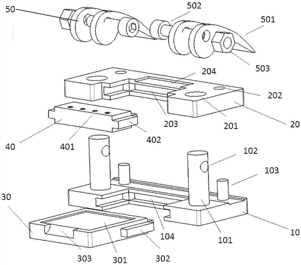
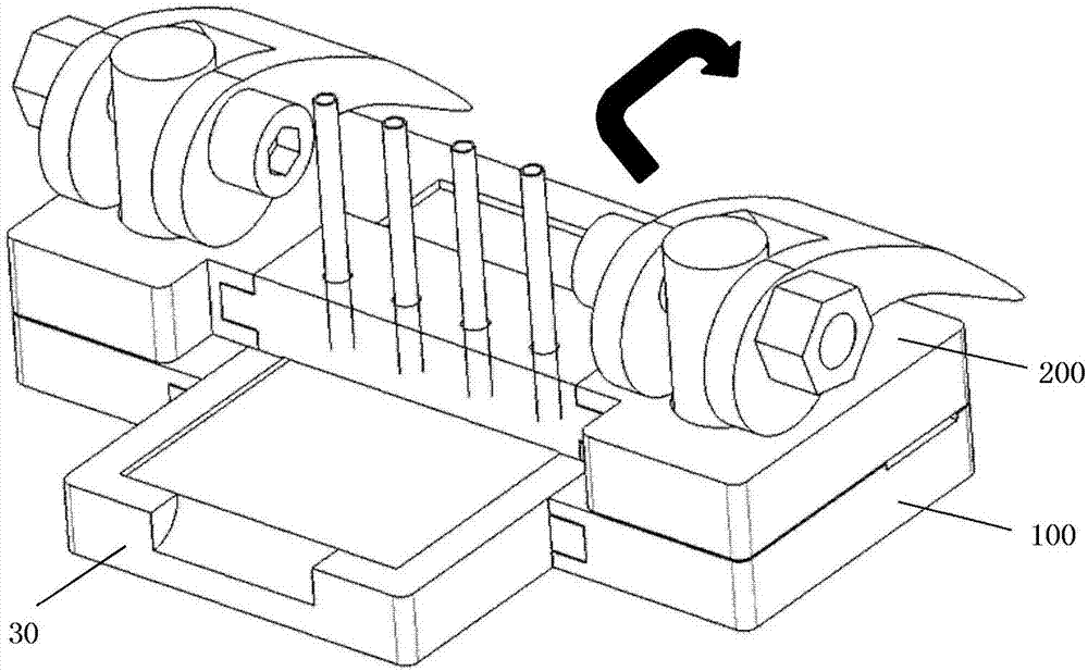
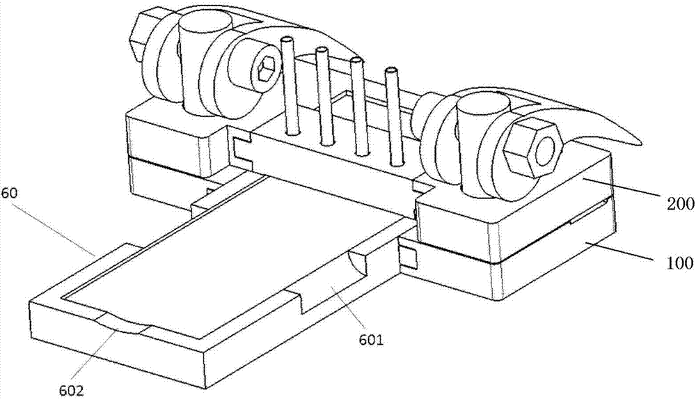
Modular fixture for microfluidic chip
A microfluidic chip, modular technology, applied in the field of biomedical detection, can solve the problems of not being able to withstand the pressure and speed of the liquid inlet, damage to the soft chip interface, limiting application and popularization, etc., to ensure effective use and monitoring The reliability, easy to carry, and the effect of avoiding pollution
- Summary
- Abstract
- Description
- Claims
- Application Information
AI Technical Summary
Problems solved by technology
Method used
Image

Examples
Embodiment Construction
[0062] In order to make the object, technical solution and advantages of the present invention clearer, the present invention will be further described in detail below in conjunction with specific embodiments and with reference to the accompanying drawings. In the present invention, the terms "including" and "comprising" and their derivatives mean inclusion but not limitation.
[0063] The term "detachable connection" in the present invention means that two parts can be connected as a whole, or one part can be detached from the other after being connected as a whole. The detachable connection can be pin joint, tenon joint Connection, insertion or hoop connection, the present invention is not limited thereto. It is preferable to adopt a connection method that can be detached by hand (without using additional tools), such as plug joint or mortise joint.
[0064]In this specification, the various embodiments described below to describe the principles of the present invention are...
PUM
 Abstract
Description
Claims
Application Information