
Fixture for steel rail forging, forging device, heat treatment system and heat treatment process

A heat treatment system and rail technology, applied in forging/pressing/hammer devices, heat treatment furnaces, heat treatment equipment, etc., can solve the problems of increased energy consumption, inconvenient quality management, short service life of rails, etc., and achieve the reduction of plant length, The effect of shortening the processing steps and reducing the processing production area

Active Publication Date: 2017-11-10
HUBEI WUTIESHANQIAO TRACK EQUIP CO LTD
View PDF6 Cites 3 Cited by
  • Summary
  • Abstract
  • Description
  • Claims
  • Application Information

AI Technical Summary

Problems solved by technology

[0004] (1) The degree of automation of the equipment is extremely low, and it needs to be transferred continuously. The entire processing procedure occupies a large area, the processing equipment is relatively scattered, and multiple stacking points need to be set up in the intermediate processing procedure, which is not convenient for workshop management. Secondly, the labor cost is high and labor High strength and extremely low production efficiency;
[0005] (2) When forging the heel of the rail, it needs to be repeatedly forged 2-3 times to form a good shape, and the noise during forging is too large, and each time the rail is forged, the rail needs to be manually rotated by 180° after the rail is heated before forging , and repeated heating during forging will also increase energy consumption;
[0006] (3) The steel rail needs to be normalized before quenching, and after normalizing, it needs to be cooled naturally, and the natural cooling of the steel rail from 950-1000 °C takes a long time to further reduce production efficiency;
[0007] (4) After the rail is cooled, it is necessary to transfer the rail to the quenching machine. When the rail head is quenched, because the water spray is used to quickly cool the rail head, the depth of the quenching layer of the rail head is relatively shallow, usually Within 5-10mm, and during spray cooling, it cools the rail head unevenly, the metallographic structure of the rail head is uneven, and bad structures such as martensite are prone to appear; secondly, the spray cooling is to atomize the water by blowing, and the water The atomization effect of the water is directly related to the quenching quality, and the atomization effect of water is affected by many factors at this time, including wind pressure, water pressure, easy blockage of nozzle holes or water column due to poor atomization of individual nozzle holes, and machine tool heating. Influenced by factors such as power, frequency, machine tool travel speed, season and weather, the stability of the equipment is poor, so not only the quality of the same root product cannot be guaranteed, but the uniformity of products between different batches is also extremely difficult to guarantee, that is, the quenching effect of the product The discreteness is large, which is not convenient for product quality management;
[0008] (5) The rail head processed by traditional technology has a shallow quenching layer, and the metallographic composition of the rail head is uneven, its wear resistance is poor, and the service life of the rail is short

Method used


Image

  • Fixture for steel rail forging, forging device, heat treatment system and heat treatment process
  • Fixture for steel rail forging, forging device, heat treatment system and heat treatment process
  • Fixture for steel rail forging, forging device, heat treatment system and heat treatment process

Examples


Embodiment 1

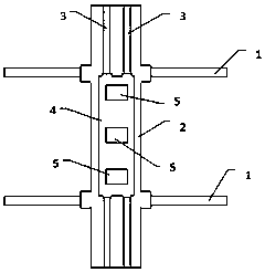
[0044] see Figure 1-2 , the present embodiment provides a claw for rail forging, the clamp includes several transverse guide rails arranged side by side, the transverse movement platform is arranged on the transverse movement platform, and several longitudinal Guide rail, the longitudinal movement platform is provided on the longitudinal movement platform, and several claws are evenly spaced and distributed in a straight line on the longitudinal movement platform; the claws include a rotating disk and a rotating disk base, and the rotating disk base can be lifted by The device is fixed on the longitudinal movement platform. There is a rectangular slot on the rotating disk. Small holes are arranged symmetrically and oppositely on the lower part of the inner wall on both sides of the slot. The first telescopic cylinder is arranged in the small hole, and the first telescopic cylinder stretches and retracts. The end of the arm is provided with a clamping plate; the periphery of t...

Embodiment 2

[0051] The present embodiment provides a kind of rail forging device that adopts above-mentioned fixture, please refer to Figure 5 The right half, the device also includes forging equipment and intermediate frequency heating furnace, the forging equipment and intermediate frequency heating furnace are distributed side by side on the side of the end of the longitudinal movement platform of the fixture; The center of the furnace mouth of the furnace is at the same height and in the same vertical plane.

[0052] The side of the forging equipment is provided with an infrared range finder, and the infrared range finder is on the same straight line as the center of the forging die mouth and the center of the intermediate frequency heating furnace mouth; the infrared range finder sends signals to the control system, and the The forging equipment and intermediate frequency heating furnace are all controlled by the control system.

[0053] In this embodiment, by adopting the fixture fo...

Embodiment 3

[0056] This embodiment provides a rail heat treatment system using the above-mentioned forging device, the heat treatment system also includes a quenching device, the quenching device is located beside the forging device, the quenching device includes a conveying platform, and the end of the conveying platform is provided with Normalizing furnace, there is also air cooling equipment between the conveying platform and the normalizing furnace, please refer to Figure 12 , the air-cooled equipment includes an air compressor, an air storage tank and a shower head, the air compressor pumps air into the air storage tank, and the air storage tank provides high-pressure airflow to the shower head; the shower head is a chamber structure, including a top plate and a On the side plates on both sides of the top plate, spray holes are evenly distributed inside the side plates and inside the top plate, and flame-retardant cotton slivers are arranged symmetrically and oppositely on the bottom...


PUM


Abstract

The invention discloses a fixture for steel rail forging, and belongs to the field of mechanical equipment. The fixture is provided with transverse and longitudinal motion platforms and a liftable device for realizing three-dimensional motion of a steel rail in all directions, and meanwhile, is provided with a rotating disc for realizing large-angle rotation of the steel rail. The invention further discloses a steel rail forging device adopting the fixture; and the device comprises a medium-frequency heating furnace, forging equipment and an infrared distance measurer, realizes full-automatic forging of the steel rail, and improves the machining efficiency. Meanwhile, the invention further discloses a steel rail heat treatment system adopting the forging device; and the system comprises a conveying platform, air cooling equipment, a normalizing furnace and a pushing table, and can further reduce machining procedures, reduce the energy consumption and improve the machining efficiency. In addition, the invention discloses a steel rail heat treatment process according to the system; and the process comprises a forging process and a quenching process, and can realize thorough hardening of a rail head and uniform quality in machining of the steel rail.

Description

technical field [0001] The invention relates to the field of rail processing equipment, in particular to a rail forging fixture, a forging device, a heat treatment system and a heat treatment process. Background technique [0002] At present, the AT point rails for railway turnouts are processed by forging and quenching at the heel of standard rails. There is a long slide rail, and the rail is hoisted by the crane to the slide rail, and then sent to the intermediate frequency heating furnace, and the heel of the rail is heated in the intermediate frequency heating furnace. After heating, the intermediate frequency heating furnace and the slide rail end Stretch the rail onto the slide rail, and extend the heated end of the rail on the slide rail into the forging die of the forging equipment for forging. At this time, during forging, the non-heated part of the rail is only placed on the slide rail. When the rail heel is forged, the rail will produce severe co-vibration, which...

Claims


Application Information

Patent Timeline
Patent Type & Authority Applications(China)
IPC IPC(8): B21J13/08B21J5/06C21D9/04B21K9/00
CPCB21J5/06B21J13/085B21K9/00C21D9/04
Inventor 邹小魁王安定李瑞雨朱磊
Owner HUBEI WUTIESHANQIAO TRACK EQUIP CO LTD
Learn More