Neutron insertion piece system and collimation mounting method thereof

An insert and neutron technology, applied in the direction of using the diaphragm/collimator, etc., can solve the problem that there is no specific public collimator structure, it is difficult to achieve accurate detection and adjustment of elevation and horizontal position, and it is difficult to ensure the alignment of neutron beamlines. Problems such as straightness and shielding effect, to achieve fast and convenient collimation installation, convenient update and maintenance, and strong adjustability

Active Publication Date: 2017-11-17
DONGGUAN NEUTRON SCI CENT
View PDF6 Cites 13 Cited by
  • Summary
  • Abstract
  • Description
  • Claims
  • Application Information

AI Technical Summary

Problems solved by technology

[0004] The Chinese patent application publication number is CN103106940 A patent, which relates to the field of neutron physics technology, and discloses a neutron collimation system of a high-voltage doubler, although the system is composed of a shield, a channel, a collimator in the channel and a detector The composition, more specifically, is to open a channel on the shielding body of the high-voltage doubler hall, the front of the shielding body is equipped with a front-stage collimator, and the channel has a built-in collimator, and the collimator built in the channel has an inner and outer two-layer structure. However, this technical solution does not specifically disclose the structure of the collimator, and it is difficult to ensure the collimation and shielding of the neutron beam in the neutron conduit
In addition, the Chinese

Method used


Image

  • Neutron insertion piece system and collimation mounting method thereof
  • Neutron insertion piece system and collimation mounting method thereof
  • Neutron insertion piece system and collimation mounting method thereof

Examples


specific Embodiment approach

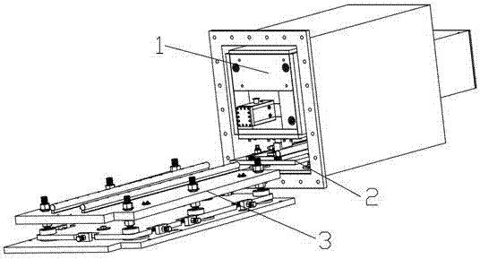
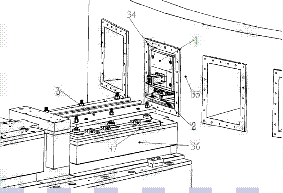
[0048] like Figure 1-11 As shown, a neutron insert system, the neutron insert system mainly includes a neutron insert 1, an internal adjustment mechanism 2 and an external adjustment mechanism 3, wherein the neutron insert 1 is installed on the In the shielding cylinder 34 , the external adjustment mechanism 3 is set on the transitional steel plate 37 , and the transitional steel plate 37 is pre-embedded on the concrete base 36 , and the neutron insert 1 is transported into and out of the shielding cylinder 34 through the external adjustment mechanism 3 .

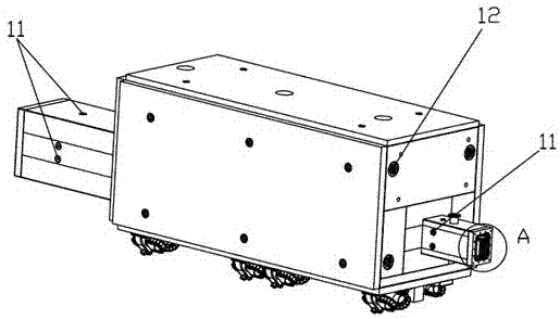
[0049] like Figure 3-7 As shown, the neutron insert 1 mainly includes a neutron conduit and a crawler slider group; the crawler slider group is installed at the bottom of the neutron conduit; the neutron conduit mainly consists of a super mirror glass 14 and a metal casing 4 Consisting of two parts, the super-mirror glass 14 refers to using glass as a substrate, depositing metal or non-metallic substances on the glass su...


PUM


Abstract

The invention relates to the technical field of a neutron scattering spectrometer and particularly relates to a neutron insertion piece system and a collimation mounting method thereof. The system comprises a neutron insertion piece, an inner adjusting mechanism in a shielding cylinder, and an outer adjusting mechanism outside the shielding cylinder, wherein the neutron insertion piece is mounted in the shielding cylinder, the inner adjusting mechanism is mounted at a bottom portion of the neutron insertion piece, the outer adjusting mechanism is arranged on a transition steel plate, the transition steel plate is pre-embedded in a concrete base station, and the neutron insertion piece is conveyed in and out of the shielding cylinder through the outer adjusting mechanism. The neutron insertion piece system is advantaged in that the structure is relatively simple, strong machinability and adjustability are realized, the deviation relationship of an actual value and a theoretical value of a target set can be acquired, update and maintenance of the neutron insertion piece are facilitated, a collimation mounting apparatus is a laser tracker and a measurement arm, collimation and mounting of the neutron insertion piece can be rapidly and conveniently realized, and replacement of the neutron insertion piece can be realized in minutes.

Description

technical field [0001] The invention relates to the technical field of neutron scattering spectrometers, in particular to a neutron insert system and a collimating installation method thereof. Background technique [0002] Neutron spectrometer mainly uses neutrons as a detection method to study the microstructure and properties of various substances. At present, the spectrometers built in various countries in the world can be divided into two categories, one is called neutron spallation source spectrometer; the other is called neutron reactor spectrometer. The neutron beam in the target station or reactor is transmitted to the spectrometer hall through neutron optical components such as neutron conduit or collimator, and then transmitted to the sample. Both the reactor and the target station need radiation protection shielding; thus neutron conduits or collimators inevitably need to pass through the radiation protection shielding layer. A neutron conduit or collimator loca...

Claims


Application Information

Patent Timeline
IPC IPC(8): G21K1/02
CPCG21K1/02
Inventor 吴延岩孙远肖松文朱涛
Owner DONGGUAN NEUTRON SCI CENT
Why Eureka
Try Eureka