Prefabricated building main body structure

A building main body and prefabricated technology, applied in the direction of building structure, construction, etc., can solve the problems of difficult standardized management, single installation method, and low degree of assembly, so as to improve on-site work efficiency, reduce environmental pollution, and reduce labor costs Effect

Pending Publication Date: 2017-11-21
北京善筑科技股份有限公司
View PDF6 Cites 14 Cited by
  • Summary
  • Abstract
  • Description
  • Claims
  • Application Information

AI Technical Summary

Problems solved by technology

[0003] Prefabricated buildings have the advantages of environmental protection and fast construction speed, and become one of the important directions of future architectural development. At present, more and more prefabricated houses are used. Most of the existing prefabricated houses adopt steel structure frame and concrete prefabricated panel system Or adopt a thin-walled light steel dense rib keel composite structure system, which has the problems of single installation method and complicated installation process
At the same time, the existing prefabricated buildings have a low degree of assembly when connecting beams and columns, and there are many wet and hot operations on site. Beams have poor flexural bearing capacity and are not suitable for large-span commercial complex buildings

Method used


Image

  • Prefabricated building main body structure
  • Prefabricated building main body structure
  • Prefabricated building main body structure

Examples


Embodiment 1

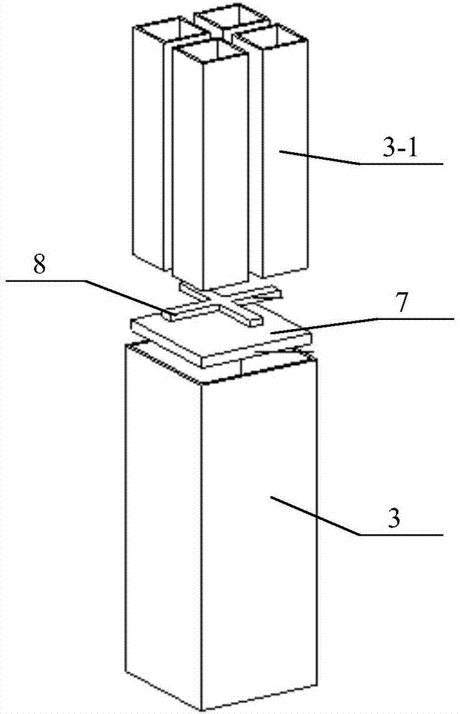
[0059] Such as Figure 5 As shown in (b), the upper part between the four mortise tubes 3-1 is provided with a partition 9 for convenient sleeve insertion, the partition 9 is a cross partition, and the width L of the cross partition is equal to the width of the cross steel plate 8 a is the same as Figure 5 As shown in (a), the material of the cross partition can be rubber, which has a certain degree of elasticity. In this way, the cross partition is placed on the upper part of the gap between the four tenon tubes 3-1 to ensure that it does not slip to the bottom of the tenon tube. After the sleeve is put on the mortise tube, the cross partition is moved to the bottom, which does not affect the insertion and has a certain buffering effect on vibration.

Embodiment 2

[0061] Such as Figure 5 As shown in (c), the two mortise tubes 3-1 that are arranged oppositely are provided with a rectangular spacer ring 10 for convenient sleeve insertion, such as a rectangular rubber ring, etc., which have certain elasticity, and the two rectangular spacer rings 10 The corners are connected as an integral structure, and two rectangular spacer rings 10 are sleeved on the opposite tenon tubes 3-1 respectively. The width a is consistent, and the width of each rectangular spacer ring 10 outside the four tenons can be set a little smaller, as long as it does not affect the implementation of the present invention.

Embodiment 3

[0063] Such as Figure 5 As shown in (d), the upper parts of the four mortise tubes 3 are provided with rectangular spacer rings 10, such as rubber rectangular rings, etc., which have certain elasticity. The width D between the two tenon tubes is the same as the width a of the cross steel plate. This can ensure that the gaps between the top and the bottom of the four tenon tubes are consistent, which is convenient for inserting the sleeve, and the width of the rectangular spacer ring outside the four tenons can be set a little smaller, as long as it does not affect the implementation of the present invention.

[0064] In Embodiment 1 to Embodiment 3, before the sleeve is inserted into the tenon tube, the separator 9 and the rectangular spacer rings 10 and 11 are all arranged on the upper part of the gap between the tenon tube 3-1 to ensure that they do not slip to the bottom of the tenon tube , when the sleeve is placed on the tenon tube, the partition 9 and the rectangular s...


PUM


Abstract

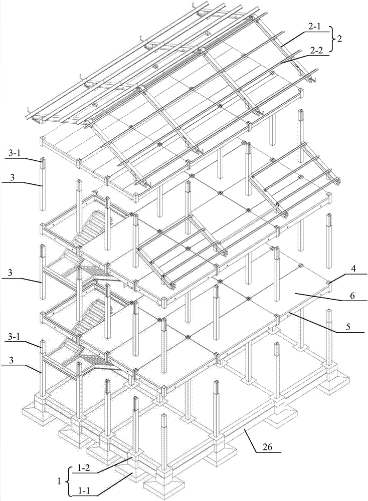
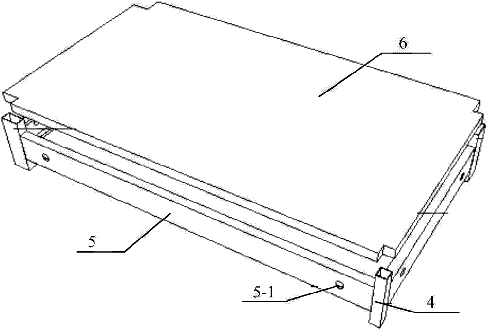
The invention discloses a prefabricated building main body structure, and relates to the technical field of constructional engineering structures. The prefabricated building main body structure comprises an independent foundation; at least one layer of floor slabs is fixedly arranged above the independent foundation; a supporting structure is arranged under each layer of the floor slabs; a roof frame structure is fixedly arranged above the top layer of the floor slabs; the floor slabs comprise a plurality of combination beam plates; the supporting structure of each layer comprises a plurality of square pipe columns; tenon pipes connected with the combination beam plates in an inserting manner are arranged on the square pipe columns; a stairway is arranged between every two vertically adjacent layers of floor slabs; the combination beam plates comprise four-corner components; steel beams are fixedly connected between the adjacent four-corner components; the upper edges of the steel beams are spaced from the top ends of the four-corner components by a certain distance; concrete slabs are poured on the steel beams; reinforcement meshes are arranged in the concrete slabs; reserved pipeline holes are formed in the side surfaces of the steel beams; and the four-corner components are sleeves matched with the tenon pipes in an inserting manner. The beam and column connection is reasonable, the mounting is convenient and the flexural capacity is high.

Description

technical field [0001] The invention relates to the technical field of construction engineering structures, in particular to a prefabricated building main structure. Background technique [0002] As a traditional industry in my country, housing construction has been in the extensive production stage for a long time, with excessive energy and raw material consumption, low industrialization, low labor productivity and low technical content. Therefore, with the rapid development of my country's economy, the industrialization of the construction industry has gradually been adopted by the society. It is valued, becomes the focus and develops rapidly. Promoting the industrialization of the construction industry is conducive to realizing energy conservation and emission reduction, promoting green and safe construction, improving project quality, improving the living environment, and promoting the upgrading of industrial structure. Prefabricated buildings are an inevitable choice to...

Claims


Application Information

Patent Timeline
Patent Type & Authority Applications(China)
IPC IPC(8): E04B1/24E04B1/58
CPCE04B1/24E04B1/2403E04B2001/2406E04B2001/2421E04B2001/2418E04B2001/246
Inventor 王衡尹国华董俊巧
Owner 北京善筑科技股份有限公司
Why Eureka
Try Eureka