UWB-technology-based automatic timing system for track and field events

An automatic timing, track and field technology, applied in the field of track and field competition automatic technology system, can solve problems such as poor real-time performance, complex system structure, huge structure, etc., and achieve the effects of simple maintenance and use, high time resolution, and high measurement accuracy.

Active Publication Date: 2017-11-24
SHENYANG AEROSPACE UNIVERSITY
View PDF5 Cites 3 Cited by
  • Summary
  • Abstract
  • Description
  • Claims
  • Application Information

AI Technical Summary

Problems solved by technology

Therefore, there are two disadvantages in the operation of this scheme: high system cost and poor real-time performance; firstly, the price of the high-speed camera is relatively expensive, and there is also a high-speed computer for image processing, which makes the cost of the entire system very high, about 20,000 yuan ; Then there is the realization of the image processing algorithm, the algorithm is more complicated, the real-time performance is poor, and there may be problems of misjudgment and end-point detection lag; based on these problems, the system has not been widely used
[0005] Endpoint detection based on RFID radio frequency identification technology, the technology is similar in principle to the ordinary bus card swiping system, and is a commonly used scheme in the current automatic timing system; the system includes two parts: radio frequency identity card and radio frequency identification station; radio frequency The identity card is installed on each athlete, and the radio frequency identification base station is laid on the finish line in a plate shape. When the athlete carries the radio frequency identification card and passes the radio frequency identification base station, the system judges that the athlete has reached the finish line and automatically calculates the time; the system has The following three disadvantages: due to the identification distance of the radio frequency identification card, there may be a risk of missed detection when reaching the end; the radio frequency identification base station has a certain width on the finish line, and the width is about 20CM, so the identification error will be 20- About 30cm; the radio frequency identification base station is laid on the ground in the form of a board, with a certain height, which is not conducive to the running of athletes, and accidents may occur in severe cases; due to these shortcomings of the system, it can only be used for low user experience In the non-precision timing system, it is used more in the automatic timing system of student track and field
[0006] End point detection based on infrared recognition, this technology is similar to TV remote control, and it is also one of the widely used end point detection technologies at present; its core technology is infrared signal coding, which consists of two parts: infrared transmitting module and infrared receiving and decoding module; The transmitting module is placed on the body of each athlete and continuously emits infrared signals, and the infrared coded signals emitted by the infrared transmitting modules worn by each athlete are different; there are n pieces of infrared receiving and decoding modules (one for each runway) steel frame It is fixed in the sky above each run, when an athlete runs from under the steel frame, the coded infrared signal emitted by the infrared transmitter module worn is not fixed on the steel frame for identification by the receiver, and it is judged as reaching the end point; the system's Disadvantages are: large structure, easy to missed detection, low precision; since each runway must have an infrared receiving module, a solid steel frame structure must be used to fix the receiver, which makes the system complex and huge. It is time-consuming and labor-intensive in maintenance and maintenance; because infrared is light, there are obstacles (such as hair, clothes) that will cause infrared signals to be unreceived, and there will be missed detections at this time; because infrared signals are not emitted in one direction, and It is launched in a fan-shaped manner, so the recognition accuracy is low, about 30CM

Method used


Image

  • UWB-technology-based automatic timing system for track and field events
  • UWB-technology-based automatic timing system for track and field events
  • UWB-technology-based automatic timing system for track and field events

Examples


Embodiment Construction

[0035] In order to more clearly illustrate the technical solutions in the embodiments of the present invention or the prior art, the following will briefly introduce the drawings that need to be used in the description of the embodiments or the prior art. Obviously, the accompanying drawings in the following description are only These are some embodiments of the present invention. For those skilled in the art, other drawings can also be obtained according to these drawings without any creative effort.

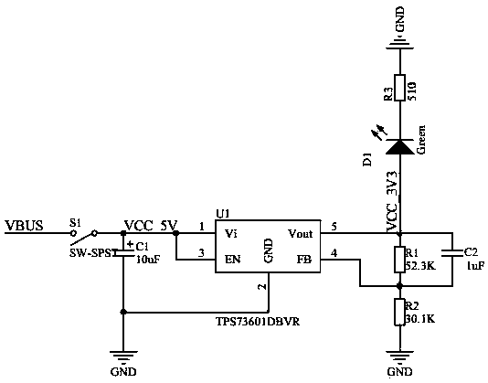
[0036] It should be noted that in this embodiment, the UWB transmitter chip DWM1000, the main control chip STM32F105RCT6, the domestic power management chip HT4928S, the lithium battery 3.7V, 650mah, the voltage regulator chip TPS3601DBVR, and the development of the embedded terminal are based on embedded Linux. The development of the application is done using the cross-platform software Qt.

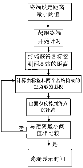
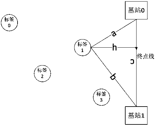
[0037] Referring to the accompanying drawings, the automatic timing system for track ...


PUM


Abstract

The invention discloses a UWB-technology-based automatic timing system for track and field events. By means of the UWB technology, electronic tags on athletes monitor the match time and the distance between the athletes and the finish line in real time through wireless communication between a base station at the finish line and an intelligent terminal; the condition that the athletes reach the finish line is analyzed and judged by means of a unique algorithm, precise distance measurement is achieved, the cost is lowered, errors are reduced, use is convenient, and safe and reliable automatic timing is achieved.

Description

technical field [0001] The invention relates to the field of sports equipment, in particular to an automatic technical system for track and field competitions based on UWB technology. Background technique [0002] The current track and field timing methods include two types: machine automatic timing and manual timing; manual timing will be completely replaced by machine automatic timing, so there are more researches on machine automatic timing. [0003] The most critical technology in the timing system is the detection of athletes reaching the finish line; at this stage, there are three types of finish point detection technologies: based on high-speed camera video capture, based on RFID and based on infrared detection; [0004] End point detection based on high-speed camera video capture technology, this technology is similar to the "Eagle Eye" technology in the Olympic Games; The camera shoots the athletes in real time, and the camera uploads the images to the computer for...

Claims


Application Information

Patent Timeline
IPC IPC(8): A63B71/06H02J7/00
CPCA63B71/0686H02J7/0047A63B2220/836A63B2220/20A63B2220/10A63B2220/62H02J2207/20H02J7/00Y02D30/70
Inventor 李玉峰张佩赵鑫王宇鹏关庆阳马立峰
Owner SHENYANG AEROSPACE UNIVERSITY
Why Eureka
Try Eureka