Four-point bending beam-based bituminous mixture interlaminar shear strength testing device

A technology of interlayer shear strength and asphalt mixture, which is applied in the direction of applying stable shear force to test material strength, measurement devices, strength characteristics, etc., can solve the problem of inability to simulate the change of compressive stress and shear stress with the depth of the road surface, and the difficulty Reasonably explain and analyze problems such as the bonding between asphalt pavement layers to achieve the effects of reducing deformation, reducing impact, and improving accuracy

Inactive Publication Date: 2017-11-24
SOUTHWEST JIAOTONG UNIV
View PDF8 Cites 12 Cited by
  • Summary
  • Abstract
  • Description
  • Claims
  • Application Information

AI Technical Summary

Problems solved by technology

However, the oblique shear test mostly uses a fixture with a fixed inclination angle, which produces a constant ratio of vertical force and horizontal force, which cannot simulate the change of compressive stress and shear stress produced by the actual pavement structure under the driving

Method used


Image

  • Four-point bending beam-based bituminous mixture interlaminar shear strength testing device
  • Four-point bending beam-based bituminous mixture interlaminar shear strength testing device
  • Four-point bending beam-based bituminous mixture interlaminar shear strength testing device

Examples


Embodiment 1

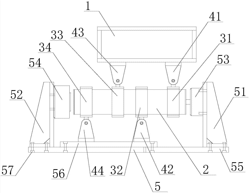
[0048] Such as figure 1 As shown, the present invention is based on the asphalt mixture interlayer shear strength testing device of the four-point bending beam method, including a loading I-beam 1, a bending beam clamp 3, a support 4 and a base 5; the loading I-beam 1, The test piece 2 and the base 5 are sequentially arranged from top to bottom; the bending beam fixture 3 includes a first bending beam fixture 31, a second bending beam fixture 32, a third bending beam fixture 33 and a fourth bending beam fixture 34; The support 4 includes a first support 41, a second support 42, a third support 43 and a fourth support 44; the first bending beam clamp 31, the second bending beam clamp 32, the third bending beam clamp 33 and the fourth bending beam fixture 34 are sequentially set on the test piece 2 along the axis of the test piece 2; the first support 41 and the third support 43 are installed on the bottom of the loading I-beam 1, and the first support 41 is hinged on the The f...

Embodiment 2

[0051] Such as Figure 14 , Figure 15 and Figure 16 As shown, in this embodiment, on the basis of embodiment 1, the size of the tested piece 2 is 50*70*280mm, Figure 15 and Figure 16 On the surface, there is no bending moment at the interlayer section of the specimen, and the shear force on the interlayer section is 11 / 15V, which is in line with the theoretical analysis results of material mechanics.

Embodiment 3

[0053] Such as figure 1 As shown, on the basis of Embodiment 1, this embodiment also includes a first baffle 51 and a second baffle 52 arranged on the top surface of the base 5; the first baffle 51 and the second baffle 52 face each other set, and the test piece 2 is located between the first baffle plate 51 and the second baffle plate 52; the first baffle plate 51 is provided with a tension and pressure sensor 53 on the surface facing the test piece 2; the second baffle plate 52 faces the test piece A horizontal jack 54 is arranged on the surface of the part 2 .

[0054] When this embodiment is implemented, the test piece 2 is loaded through the second baffle 51, and the force is monitored by the tension and compression sensor 53 on the first baffle 51. Since the first bending beam clamp 31 and the second bending beam The fixture 32, the third bending beam fixture 33 and the fourth bending beam fixture 34 are respectively hinged to the first support 41, the second support 42...


PUM


Abstract

The invention discloses a four-point bending beam-based bituminous mixture interlaminar shear strength testing device. A first support and a third support are arranged at the bottom of a loaded I-shaped beam, the first support is hinged to a first bending beam clamp, and the third support is hinged to a third bending beam clamp; a second support and a fourth support are arranged at the top of a base, the second support is hinged to a second bending beam clamp, and the fourth support is hinged to a fourth bending beam clamp. By regulating the positions of the bending beam clamps and the supports, the four-point bending beam-based bituminous mixture interlaminar shear strength testing device can guarantee that the vertical load applied onto a test piece corresponds to the designed length of a moment arm, and due to the interaction of vertical load and hinging, the interlaminar of a test piece only bears shearing load without the influence from bending moment stress, thus facilitating reasonable explanation and analysis on the interlaminar cementation situation of bituminous pavements in a pure shearing state, and simultaneously lightening the influence of rigidity of the bending beam clamp on testing results.

Description

technical field [0001] The invention relates to the technical field of road engineering, in particular to an asphalt mixture interlayer shear strength testing device based on a four-point bending beam method. Background technique [0002] Asphalt pavement is a multi-layer system structure composed of different structural layers. In the process of pavement structure design and construction, it is generally assumed that each structural layer is in a completely continuous state. Then, a large number of early pavement disease investigations show that the combination of asphalt pavement layers is one of the important factors affecting the service life of asphalt pavement, especially in large longitudinal slope road sections, small radius road sections, and acceleration and braking areas. The layer will generate a large horizontal load, and the shear stress generated between the layers of the pavement structure will be several times larger than that of the general road section. A...

Claims


Application Information

Patent Timeline
IPC IPC(8): G01N3/24G01N3/02G01N3/04
Inventor 任东亚艾长发阿里·拉赫曼阳恩慧邱延峻安少科李佳
Owner SOUTHWEST JIAOTONG UNIV
Why Eureka
Try Eureka