Method for measuring free hemoglobin by double-optical-path-length and multi-position modulation fluorescent excitation light source
A fluorescence excitation and hemoglobin technology, applied in fluorescence/phosphorescence, measurement devices, material excitation analysis, etc., can solve the problems of inability to completely eliminate the influence of spectral background noise, fluorescence self-absorption, spectral nonlinearity, etc., to achieve inhibition of blood scattering, Measure targeted, informative effects
- Summary
- Abstract
- Description
- Claims
- Application Information
AI Technical Summary
Problems solved by technology
Method used
Image
Examples
Embodiment 1
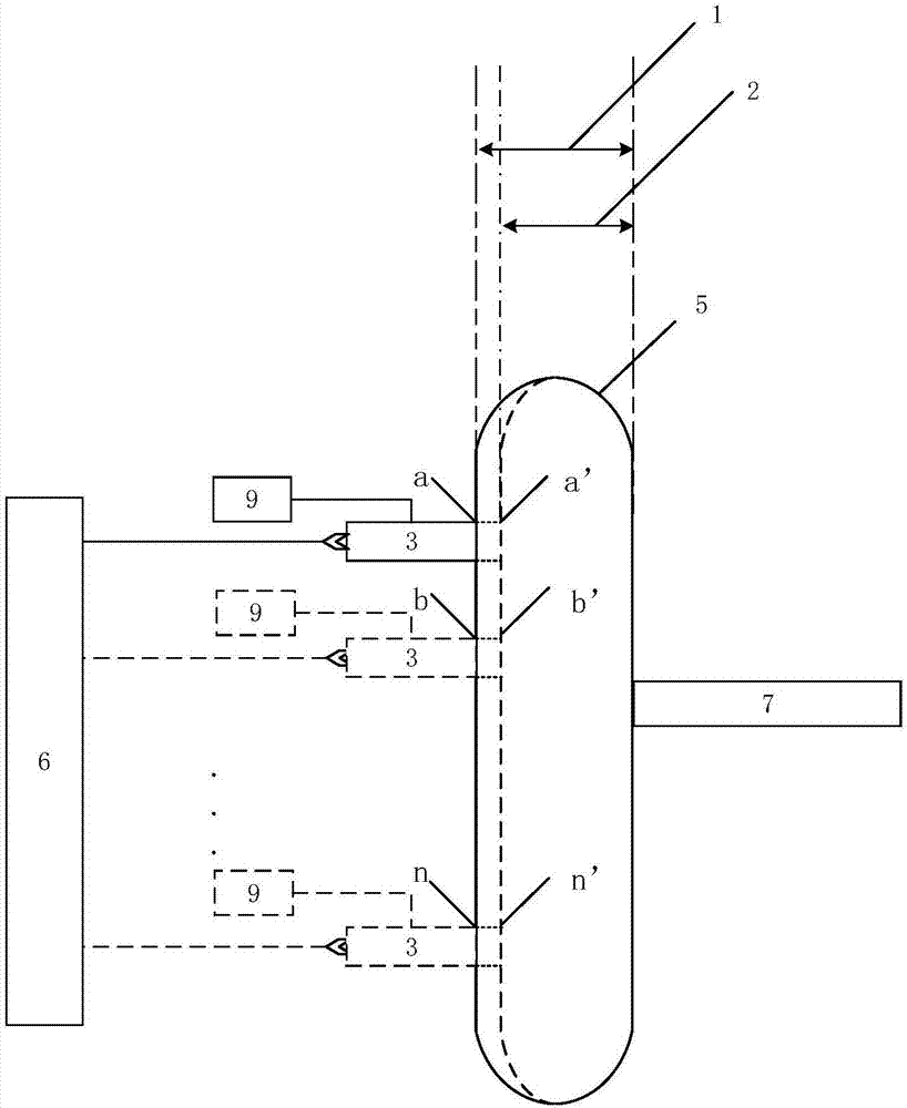
[0060] The embodiment of the present invention provides a method for measuring free hemoglobin with a dual optical path and multi-position modulated fluorescence excitation light source. The devices used are such as figure 2 As shown, it includes: a fluorescent excitation light source 3 , a blood bag 5 , a displacement platform 6 , a spectrum receiving device 7 and a modulating device 9 .
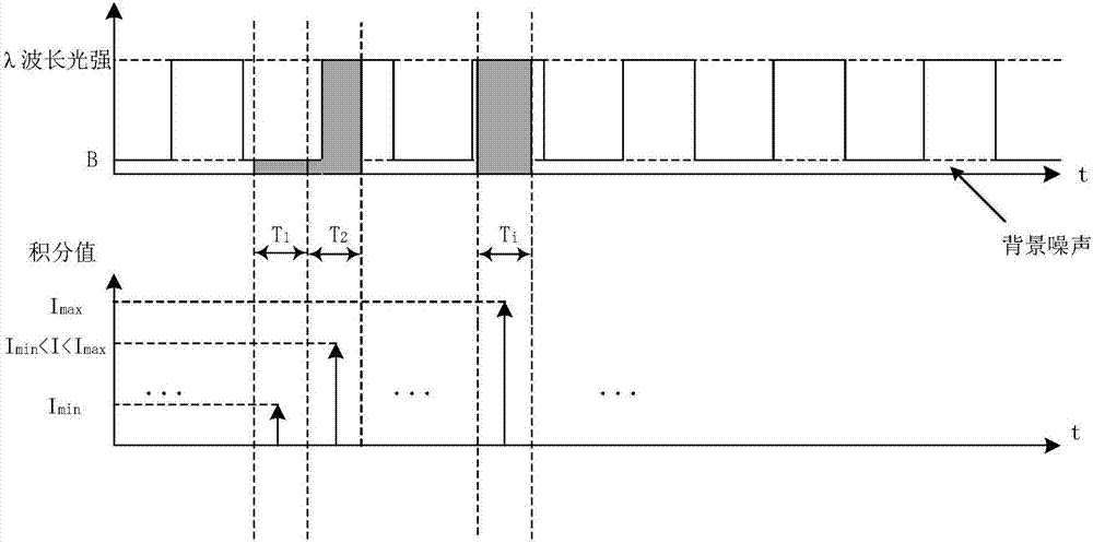
[0061] Wherein, ensure that the light exit port of the fluorescence excitation light source 3 and the incident slit of the spectrum receiving device 7 are close to the blood bag 5, the modulation device 9 modulates the fluorescence excitation light source 3 to make it emit a square wave light signal, and the fluorescence excitation light source 3 at position a Under the two optical paths: position a (corresponding to the first optical path 1) and position a' (corresponding to the second optical path 2) excite the blood sample in the blood bag 5, and the fluorescence spectrum is collected by...
Embodiment 2
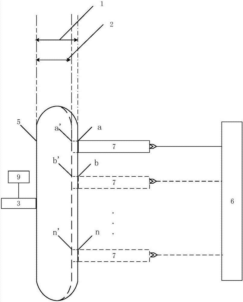
[0070] The difference between the embodiment of the present invention and embodiment 1 is only that the fluorescence excitation light source 3 and the movement mode of the spectrum receiving device 7 are different, see the following description for details:
[0071] see image 3 To ensure that the light outlet of the fluorescence excitation light source 3 and the incident slit of the spectrum receiving device 7 are close to the blood bag 5, the modulation device 9 modulates the fluorescence excitation light source 3 to make it emit a square wave light signal, and the fluorescence excitation light source 3 controls the blood bag 5 The blood sample is excited, and the spectrum receiving device 7 collects the fluorescence spectrum at the position a under the double optical path: position a and position a'. Control the spectrum receiving device 7 to move to position b through the displacement platform 6, and collect the fluorescence spectrum under the double optical path at positi...
Embodiment 3
[0076] During specific implementation, due to the limitation of the space structure, it may occur that the fluorescence excitation light source 3 and the spectrum receiving device 7 cannot be close to the blood bag 5. At this time, an optical fiber can be respectively arranged at the fluorescence excitation light source 3 and the spectrum receiving device 7 , as the incident fiber 4 and the exit fiber 8 .
[0077] see Figure 4 , the modulation device 9 modulates the fluorescence excitation light source 3 to make it emit a square wave light signal, the fluorescence excitation light source 3 excites the blood sample in the blood bag 5 through the incident optical fiber 4, the fluorescence spectrum is collected by the spectrum receiving device 7 through the exit optical fiber 8, and the incident optical fiber 4 and the outgoing optical fiber 8 are respectively close to the blood bag 5, the incident optical fiber 4 is at the position a, and the fluorescence excitation light sourc...
PUM
 Abstract
Description
Claims
Application Information
 - R&D
- Intellectual Property
- Life Sciences
- Materials
- Tech Scout
- Unparalleled Data Quality
- Higher Quality Content
- 60% Fewer Hallucinations
Browse by: Latest US Patents, China's latest patents, Technical Efficacy Thesaurus, Application Domain, Technology Topic, Popular Technical Reports.
© 2025 PatSnap. All rights reserved.Legal|Privacy policy|Modern Slavery Act Transparency Statement|Sitemap|About US| Contact US: help@patsnap.com


