High-speed milling cutter abrasion vision in-place monitoring system and method

A technology for tool wear and high-speed milling, applied in the field of inspection, can solve the problems of complex shape of milling cutter, low imaging accuracy, light source scattering, etc., and achieve the effects of accurate monitoring, high image acquisition quality and less scattering

Pending Publication Date: 2017-11-28
詹白勺 +1
View PDF7 Cites 2 Cited by
  • Summary
  • Abstract
  • Description
  • Claims
  • Application Information

AI Technical Summary

Problems solved by technology

[0004] The traditional machine vision method mainly collects the image of the tool flank, and then judges the degree of tool wear after image processing. Howev

Method used


Image

  • High-speed milling cutter abrasion vision in-place monitoring system and method
  • High-speed milling cutter abrasion vision in-place monitoring system and method
  • High-speed milling cutter abrasion vision in-place monitoring system and method

Examples


Example Embodiment

[0026] In order to better understand the present invention, the technical solution of the present invention will be further described below in conjunction with the description of the drawings and specific embodiments, see Figure 1 to Figure 9 .

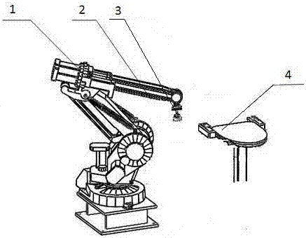
[0027] The high-speed milling tool wear vision on-site monitoring system implemented according to the present invention includes a manipulator, which is a six-degree-of-freedom manipulator, which can teach and learn according to different detection positions and assembly positions, and store the optimal path coordinates for reproduction. The base of the manipulator is fixed on the ground, and the end of the manipulator is equipped with a clamp for clamping the lens. In order to facilitate the adjustment of the position of the lens, the clamp adopts a pneumatic clamp. The use of the six-degree-of-freedom manipulator makes it possible to monitor the tool stop gap in situ, and the system flexibility is enhanced.

[0028] In order to ob...


PUM


Abstract

The invention relates to the technology of cutter monitoring, in particular to a high-speed milling cutter abrasion vision in-place monitoring system and method. The system comprises a mechanical hand, a clamp, an industrial microscope lens and an industrial personal computer. The mechanical hand is fixedly installed on a ground foundation. The clamp is installed at the tail end of the mechanical hand. The industrial microscope lens is clamped on the clamp and electrically connected with the industrial personal computer, and obtained workpiece surface image data is transmitted to the industrial personal computer. The monitoring method comprises the steps that the equipment is prepared; the mechanical hand demonstrates; a standard block database is set up; and in-place detection is carried out. According to the system and the method, the industrial microscope lens obtains an image of the machined surface of a workpiece, as the milled surface is a plane, the problems of scattering and the like do not occur easily, the image obtaining quality is high, the surface quality data can be obtained accurately, and thus the abrasion condition of a cutter can be monitored accurately. The mechanical hand selects to carry out measurement during an interval of cutter stopping, and in-place detection is achieved in the cutter machining process.

Description

technical field [0001] The invention relates to detection technology, in particular to a visual on-site monitoring system and method for high-speed milling tool wear. Background technique [0002] Ultra-high-speed cutting has the advantages of high material removal rate, small cutting force, fast cutting heat transmission, high processing precision, and good processing quality. It has been widely used in aerospace, automobile, mold and other industries, and is an important development direction of modern processing technology. Ultra-high-speed cutting is also widely used in the processing of small-sized parts with complex structures, because the total material removal rate is relatively low, roughing and finishing can be completed in one process, and the use of ultra-high-speed cutting is very economical. However, the processing features are small, and the size of the tool used for processing is also reduced accordingly. The smaller the tool size, the more sensitive it is to...

Claims


Application Information

Patent Timeline
IPC IPC(8): B23Q17/09B23Q17/24
CPCB23Q17/09B23Q17/24B23Q17/2457
Inventor 詹白勺罗勇波吴意囡
Owner 詹白勺
Why Eureka
Try Eureka