High-RF-frequency analog fiber-optic links using optical signal processing

A kind of optical signal and signal technology, applied in optical fiber transmission, optical fiber radio, electrical components, etc., can solve the problems of high noise index, low dynamic range, limitation, etc., and achieve the effect of advanced implementation scheme and improvement, high performance level

Inactive Publication Date: 2017-11-28
EOSPACE
View PDF5 Cites 1 Cited by
  • Summary
  • Abstract
  • Description
  • Claims
  • Application Information

AI Technical Summary

Problems solved by technology

These problems are due to the fact that although optical modulators (used to convert RF electrical signals into optical signals for signal transmission through optical fibers) and photodetectors (used to convert optical signals transmitted through optical return RF signal) can operate at very high RF frequencies, but they are less efficient at higher RF frequencies
In addition, the photodetectors capable of operating at very high RF frequencies are very small in size, which is necessary for operation at higher frequencies, and therefore only capable of limited optical power handling
This limited optical power handling problem of high frequency photodetectors means that higher optical power sources cannot be used
Limiting optical power at the photodetector means limited RF fiber link performance in terms of low link loss, high noise figure, and low dynamic range
These issues limit the current implementation of fiber optic transmission of RF signals at very high RF (20->100GHz) frequencies

Method used


Image

  • High-RF-frequency analog fiber-optic links using optical signal processing
  • High-RF-frequency analog fiber-optic links using optical signal processing
  • High-RF-frequency analog fiber-optic links using optical signal processing

Examples


Embodiment Construction

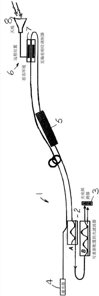
[0043] Such as figure 1 As shown, the basic filter system 1 has two reconfigurable optical filters 2 connected in series. The first filter A is reconfigured to attenuate primarily only the optical power of the carrier by a certain amount, with minimal impact on the modulation sideband signal. The optical frequency transmission spectrum of the first filter is set to be symmetrical with respect to the optical carrier in the optical frequency domain. To minimize attenuation of the signal being modulated, the period of the delay line filter should be set to maximize the transmission of the modulation sideband frequencies. In general, many other optical filters can also be used for this task, including narrowband Fabry-Perot, fiber Bragg gratings, etc., which attenuate only the carrier signal power.

[0044] The second filter B is used to demodulate the phase modulated signal and provide the result to the balanced photodetector 3 . A high power laser source 4 provides laser carr...


PUM


Abstract

Wide band phase modulators used with high power laser carriers convert high-frequency RF signals to phase-modulated optical signals. Higher laser optical power to the modulator produces larger RF signal sidebands. A carrier attenuation filter passes the attenuated carrier and non- attenuated RF modulation sidebands. Carrier attenuation leaves the larger RF signal sidebands. A demodulation filter used with a photodetector or a balanced photodetector pair converts the phase-modulated optical signal back to an electrical signal. Carrier-only attenuation allows high power laser use, avoids photodetector damage or saturation, and provides increased RF link gain, low noise figure (NF) and high spurious-free dynamic range (SFDR). Filtered-out carrier power fed back to the laser source increases to overall system efficiency. An additional optical delay filter with dual outputs used with a polarization multiplexer or a coherent combiner coupler combines signal power to a single photodetector to further increase electro-optic signal conversion efficiency.

Description

Background technique [0001] Current analog fiber optic links utilizing intensity modulators are used in both military, aerospace and commercial applications for transmitting analog radio frequency (RF) signals from antennas. Current fiber optic links have limited performance, especially at high RF frequencies (10 to >100 GHz), due to reduced conversion efficiency due to modulator limitations at higher RF frequencies, and damage due to nonlinear saturation Before that happened, small-area high-frequency photodetectors had limited optical power-handling capabilities. These limitations caused by modulators and photodetectors severely limit the performance and implementation feasibility of conventional RF fiber optic links for these high RF frequency signal transmissions. [0002] The present invention is an extension of US Patent No. 7,660,491 filed by EOSapce Corporation on February 9, 2010 and invented by the same inventor, Suwat Thaniyavarn. [0003] Current analog RF fib...

Claims


Application Information

Patent Timeline
Patent Type & Authority Applications(China)
IPC IPC(8): H04B10/2575H04B10/67
CPCH04B10/25752H04B10/25758H04B10/675
Inventor 素瓦·他尼亚瓦恩
Owner EOSPACE
Why Eureka
Try Eureka