
Two-dimensional optical phased array

An optical phased array and array element technology, applied in the field of optical phased arrays, can solve the problem that the rectangular phased array grating lobe suppression effect is not very ideal, the array element distribution is not the same, and the two-dimensional large angle range cannot be effectively achieved. problem, to achieve the effect of single beam formation, low processing difficulty, suppression of grating lobes and multi-level effects

Active Publication Date: 2017-12-01
NANJING UNIV OF AERONAUTICS & ASTRONAUTICS
View PDF5 Cites 16 Cited by
  • Summary
  • Abstract
  • Description
  • Claims
  • Application Information

AI Technical Summary

Problems solved by technology

The phased array itself is for beam scanning in a large angle range. Most of the existing optical phased array structures are rectangular. Due to its asymmetry, for beam formation with different main lobe angles, in order to effectively suppress the grating lobe, the best The distribution of array elements is often different, which determines that the density-weighted rectangular optical phased array suppressed by grating lobes cannot effectively achieve a two-dimensional large-angle range
At the same time, due to the limitation of the number of array elements and the spacing between adjacent array elements, the suppression effect of rectangular phased array grating lobes is not very ideal

Method used


Image

  • Two-dimensional optical phased array
  • Two-dimensional optical phased array
  • Two-dimensional optical phased array

Examples


Embodiment Construction

[0018] The technical scheme of the present invention is described in detail below in conjunction with accompanying drawing:

[0019] The purpose of the present invention is to: realize the grating lobe suppression of the large-interval optical phased array and the two-dimensional large-angle beam scanning; Suppress grating lobe technology, effectively suppress grating lobes and multi-stage effects, and use the circular phased array, equiangular spacing, high symmetry and compact spatial distribution of array elements to ensure beam scanning in a two-dimensional large-angle range.

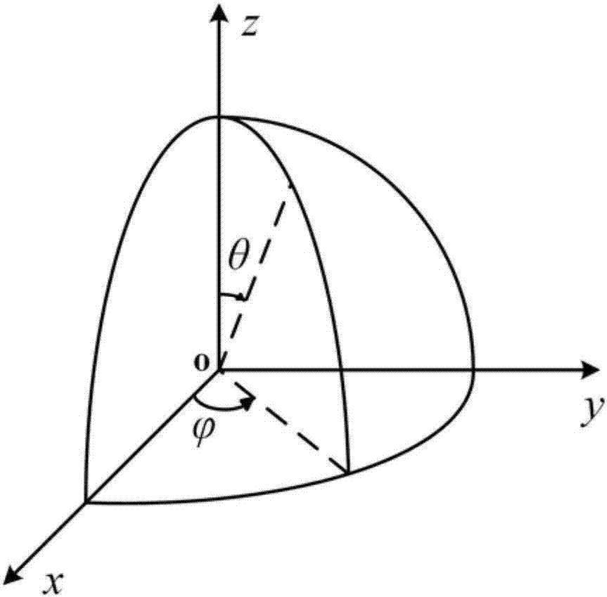
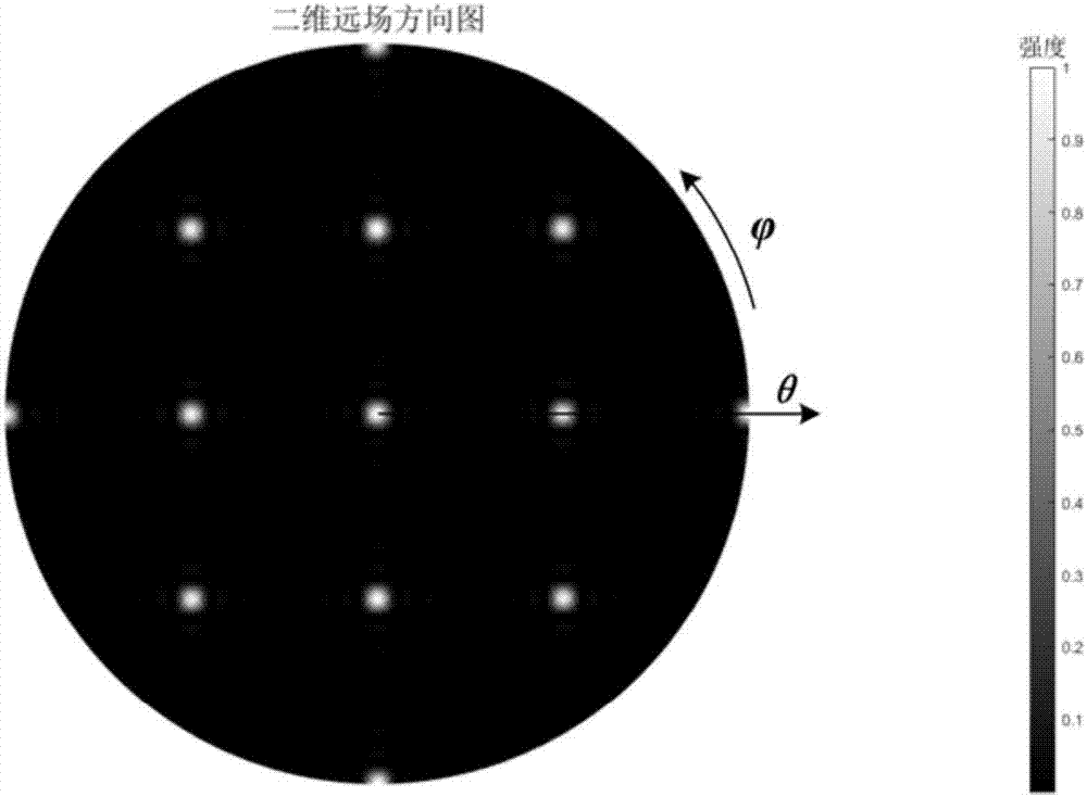
[0020] The structure of the two-dimensional optical phased array of the present invention is as follows figure 1 As shown, with one of the array elements as the center of the circle, the rest of the array elements are divided into several groups. Each group of array elements and the center of the circle form a radial line array. The structure of each line array is the same and is equal along the cir...


PUM


Abstract

The invention discloses a two-dimensional optical phased array. The two-dimensional optical phased array can be applied to multiple technical fields, such as laser radar, biomedical imaging, holographic imaging and ultra-high data rate communication. Array elements of the two-dimensional optical phased array are a set of point light sources with the same frequency, the phased array takes one of the array elements as the center of the circle, and the other array elements are evenly divided into a plurality of groups; each group of array elements and the center of the circle form a radial linear array, and the linear arrays have the same structures and are distributed at equiangular intervals in the circumferential direction. The structure of the two-dimensional optical phased array has the characteristics of a circular shape, equiangular intervals, high symmetry, compact spatial distribution of the array elements and the like, and therefore, the two-dimensional optical phased array has the advantages of low in processing difficulty, strong in inhibitive capability of grating lobes, large in two-dimensional scanning range and the like; besides, based on a non-uniform array element distribution grating lobe inhibiting technique, the phases of the array elements of the phased array are controlled so as to achieve beam formation and imaging, and the grating lobes and a multi-level effect can be effectively inhibited; in addition, single beam formation is achieved, and meanwhile the beam scanning resolution is high.

Description

technical field [0001] The invention relates to an optical phased array, in particular to a two-dimensional optical phased array, which can be applied to many technical fields such as laser radar, biomedical imaging, holographic imaging and ultra-high data rate communication. Background technique [0002] In recent years, optical phased arrays have been widely used in lidar, biomedical imaging, and wide-bandwidth spatial optical communication. Optical phased array is a new beam steering technology, which is similar to the characteristics of microwave phased array antenna scanning. It can realize fast scanning in free space through phase delay without moving or rotating the device. Compared with microwave phased array, due to its much smaller wavelength, optical phased array has the advantages of high resolution, confidentiality and chip level. However, limited by the current manufacturing process level, the element spacing of current optical phased arrays is usually much la...

Claims


Application Information

Patent Timeline
IPC IPC(8): G02F1/29
CPCG02F1/292
Inventor 张方正张道成潘时龙
Owner NANJING UNIV OF AERONAUTICS & ASTRONAUTICS
Learn More