Vertical shaft tunnel boring machine by shaft sinking method and construction method of tunnel boring machine

A technology for roadheaders and shafts, which is applied in shaft equipment, sinking, and earthwork drilling and mining, and can solve problems such as high risk, low degree of mechanization, and low efficiency, and achieve fast construction speed, convenient operation, and wide adaptability Effect

Active Publication Date: 2017-12-12
CHINA RAILWAY ENGINEERING EQUIPMENT GROUP CO LTD
View PDF8 Cites 27 Cited by
  • Summary
  • Abstract
  • Description
  • Claims
  • Application Information

AI Technical Summary

Problems solved by technology

[0004] In view of the deficiencies in the above-mentioned background technology, the present invention proposes a caisson shaft boring machine and its

Method used


Image

  • Vertical shaft tunnel boring machine by shaft sinking method and construction method of tunnel boring machine
  • Vertical shaft tunnel boring machine by shaft sinking method and construction method of tunnel boring machine
  • Vertical shaft tunnel boring machine by shaft sinking method and construction method of tunnel boring machine

Examples


Embodiment 1

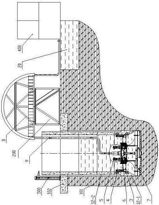
[0026] Embodiment 1: as Figure 1-3 As shown, a caisson shaft boring machine includes a drive system, a control system, and a detection system. The drive system provides the total power for the entire device, the control system controls the execution of the entire device's actions, and the detection system monitors the working status of the entire device at any time. ; Also includes interconnected tunneling mechanism 100, pipe arrangement 200, wellbore lifting mechanism 300 and slurry separation system 400 and auxiliary pressurization mechanism 500, pipe arrangement 200, wellbore lifting mechanism 300 and slurry separation system 400 and The auxiliary pressurization mechanism 500 is located on the wellhead ring beam 102 on the ground 101. The auxiliary pressurization mechanism 500 can apply downward pressure on the standard pipe joint to make it sink smoothly. The wellbore lifting mechanism controls the sinking speed of the wellbore ; A pipe-discharging mechanism 200 is arrang...

Embodiment 2

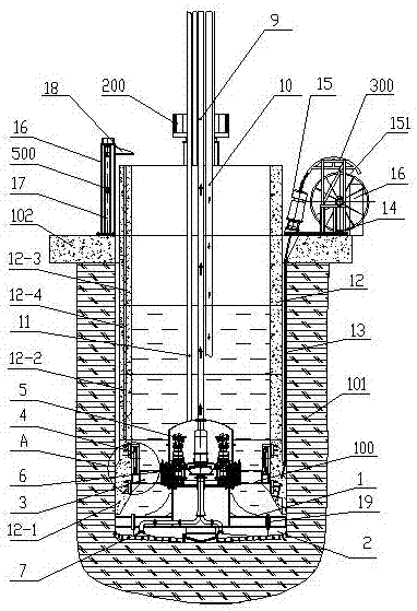
[0037] Example 2, such as Figure 1-3 As shown, a caisson method shaft boring machine, the shaft lifting mechanism 300 includes a lifting bracket 14, a lifting jack 15 and a lifting pump station 16, the lifting jack 15 is connected with the lifting pump station 16, and the lifting bracket 14 is provided with a On the reel 151 wound with the steel strand 13, the steel strand 13 passes through the lifting jack 15 and is connected with the bottom pipe joint 12-1 at the bottom of the well shaft 12, which can intermittently and continuously lift larger heavy objects until the design required Height, the system can realize synchronous lifting of multiple units. This device has the characteristics of stable lifting, safety, adjustable speed, reasonable structure design, flexible hoisting, and convenient maintenance.

[0038] Further, the auxiliary pressurization mechanism 500 includes a pressurization support 16, a pressurization cylinder 17 is provided at the bottom of the pressuriz...


PUM


Abstract

The invention provides a vertical shaft tunnel boring machine by a shaft sinking method and a construction method of the tunnel boring machine, and solves the problems of low mechanization degree and efficiency, high risk and the like of devices and construction methods in the prior art. The tunnel boring machine comprises a tunneling mechanism, a pipe arrangement mechanism, a shaft lifting mechanism, a slurry separation system and an auxiliary pressure mechanism are mutually connected, the pipe arrangement mechanism, the shaft lifting mechanism, the slurry separation system and the auxiliary pressure mechanism are positioned on an over-ground wellhead ring beam, the tunneling mechanism comprises a tunneling shell, a cutter head is arranged at the front end of the tunneling shell, a driving fixing frame is arranged at the rear end of the tunneling shell, a feeding device and a driving device are arranged on the driving fixing frame, and the feeding device and the cutter head are connected with the driving device. The tunnel boring machine has mechanized excavation, sludge discharge and support functions and is operated on the ground, safe and reliable, underground operators are omitted in the working process of the vertical shaft tunnel boring machine, traditional shaft bottom excavation modes are changed, construction risks are greatly reduced, and operating efficiency is improved.

Description

technical field [0001] The invention relates to the technical field of underground shaft construction equipment and its construction method, in particular to a caisson shaft boring machine and its construction method. Background technique [0002] The caisson method shaft boring machine is a special construction machine for shaft excavation. It has the functions of excavating and cutting soil, conveying muck, constructing shaft walls, and measuring and correcting deviations in shafts. It involves geology, civil engineering, machinery, mechanics, hydraulics, and electrical , control, measurement and other disciplines. [0003] At present, in the construction of underground projects, such as the construction of underground fortifications such as shield starting and receiving shafts, mining shafts, tunnel ventilation shafts, underground fortification shafts, and underground parking lots, shafts are the most convenient channel. At present, the construction of shafts mostly adop...

Claims


Application Information

Patent Timeline
IPC IPC(8): E21D1/03E21D1/06
CPCE21D1/03E21D1/06Y02E10/20
Inventor 杨聚辉肖威王伟卓兴建贾连辉朱英周倩
Owner CHINA RAILWAY ENGINEERING EQUIPMENT GROUP CO LTD
Why Eureka
Try Eureka