
Gas storage and heat storage integrated hot dry rock reheating compressed air energy storage system

A technology of compressed air energy storage and hot dry rock, which is applied in the field of physical energy storage, can solve the problems of difficult utilization of compression heat, high power generation cost, and poor economy, so as to reduce the difficulty of drilling wells, reduce the throttling effect, and improve efficiency Effect

Active Publication Date: 2017-12-12
XI AN JIAOTONG UNIV
View PDF8 Cites 20 Cited by
  • Summary
  • Abstract
  • Description
  • Claims
  • Application Information

AI Technical Summary

Problems solved by technology

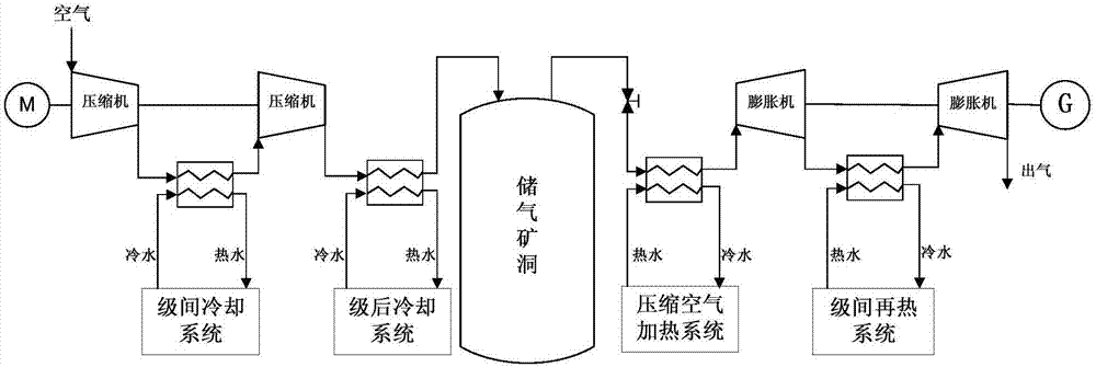
In order to improve the performance of the compressor, cooling is required between the compressor stages, and a large amount of compression heat is difficult to be utilized
[0004] One of the important reasons why the compressed air energy storage system is difficult to be applied in large-scale industrialization so far is that it needs to consume fuel for heating in the process of energy release and power generation. Natural gas fuel is usually used for heating. As a result, the compressed air energy storage system has high power generation cost, poor economy and Additional Pollution and Carbon Emissions

Method used


Image

  • Gas storage and heat storage integrated hot dry rock reheating compressed air energy storage system
  • Gas storage and heat storage integrated hot dry rock reheating compressed air energy storage system
  • Gas storage and heat storage integrated hot dry rock reheating compressed air energy storage system

Examples


Embodiment Construction

[0032] The present invention will be described in further detail below in conjunction with the accompanying drawings.

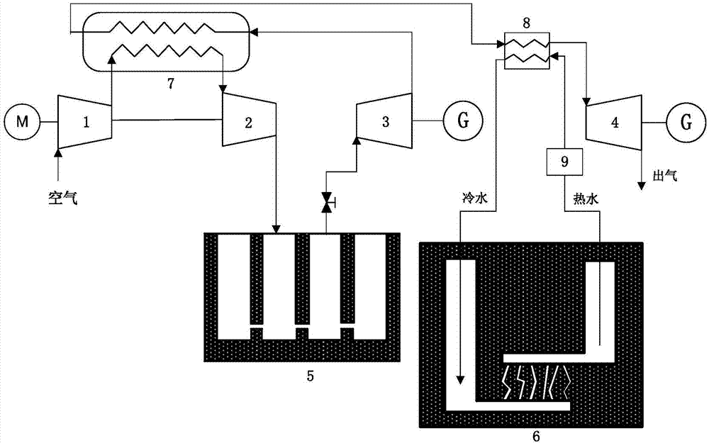
[0033] see figure 2 with image 3 , the present invention includes a compressor, a first expansion unit 3, a second expansion unit 4, an underground gas storage well group 5, a hot dry rock heating system 6, a heat accumulator 7 for storing compression heat, and a heat exchanger 8; the compressor There are several motors connected by couplings.

[0034] In order to increase the gas storage pressure and reduce the power consumption of the compressor, the compression part adopts multi-stage compression heat storage interstage cooling. The compressor is usually 2 to 3 stages. This article takes 2 stages as an example; in order to increase the workability of compressed air, improve In terms of system efficiency, the expansion part adopts multi-stage expansion and inter-stage reheating, and the expansion unit is usually 2 to 3 stages. This article takes 2 stage...


PUM


Abstract

The invention relates to a gas storage and heat storage integrated hot dry rock reheating compressed air energy storage system. The gas storage and heat storage integrated hot dry rock reheating compressed air energy storage system comprises a plurality of compressors and a plurality of expansion units, wherein the compressors are connected with a motor through couplings; the adjacent compressors are connected with one another through heat accumulators; the last-stage compressor is connected with an inlet of an underground gas storage well group; an outlet of the underground gas storage well group is connected with the first expansion unit; the first expansion unit is connected with a gas flow inlet of a heat exchanger through a heat accumulator; a gas flow outlet of the heat exchanger is connected with the second expansion unit; a working medium inlet and a working medium outlet of the heat exchanger are connected with a hot dry rock heat collecting system through pipes to form a circulation loop; the heat exchanger and the hot dry rock heat collecting system form a reheating system; when the number of the expansion units is greater than 2, reheating systems are separately arranged among the adjacent expansion units behind the first expansion unit. Heat of interstage cooling of the compressors is recycled in a compression stage, air of interstage reheating is preheated in an energy releasing stage, heat loss of the system is reduced effectively, and the efficiency of the system is improved.

Description

technical field [0001] The invention belongs to the technical field of physical energy storage, and in particular relates to a hot dry rock reheating compressed air energy storage system integrating gas storage and heat storage. Background technique [0002] With the depletion of traditional fossil energy and the increasing environmental problems, the utilization of renewable energy has received more and more attention. The inherent randomness and volatility of renewable energy such as wind energy and solar energy have brought huge challenges to the development of renewable energy, but energy storage technology can effectively solve this problem. At the same time, the construction of smart grid also urgently needs energy storage system as a supporting technology. Among the existing energy storage technologies, compressed air energy storage is recognized as the most promising physical energy storage technology at home and abroad. [0003] The temperature resistance of the g...

Claims


Application Information

Patent Timeline
IPC IPC(8): F17C5/06F17C13/00F28D20/00F24J3/08F01D15/10
CPCF01D15/10F17C5/06F17C13/00F17C2221/031F17C2223/0123F17C2227/0157F24T10/10F28D20/00Y02E10/10Y02E60/14
Inventor 王焕然李丞宸李瑞雄张淑宇
Owner XI AN JIAOTONG UNIV
Learn More