
Fully hydraulic intelligent workover rig

A workover rig and full hydraulic technology, which is applied in drilling equipment, earthwork drilling, drilling pipes, etc., can solve problems such as high risk, harsh working environment at the wellhead, and failure to realize the function of pressing down the tubing string, so as to improve safety , Easy installation and labor-saving effect

Inactive Publication Date: 2017-12-15
YANTAI JEREH PETROLEUM EQUIP & TECH CO LTD
View PDF7 Cites 110 Cited by
  • Summary
  • Abstract
  • Description
  • Claims
  • Application Information

AI Technical Summary

Problems solved by technology

[0002] In the traditional oilfield workover operations, the workover rig uses the drawworks to lift the hoisting system to realize the lifting and lowering of the tubing string, which cannot realize the function of the tubing string to press down the well, that is, the workover rig does not have automatic injection into the well The down pressure cannot overcome the lifting force of the fluid in the well on the tubing string, let alone realize the automatic blowout prevention and relief in the tubing string in the well
There is another important issue. On-site workover operations in the oil field require several workers to do wellhead operations such as pipe arrangement and pipe transfer, as well as walkway installation and blowout preventer installation before operations. The harsh working environment at the wellhead is extremely dangerous. High, in order to reduce the number of operators, reduce the cost of oilfield workover operations, improve workover efficiency, and realize the automation and intelligence of the workover rig, a fully hydraulic intelligent workover rig was designed and developed.

Method used


Image

  • Fully hydraulic intelligent workover rig
  • Fully hydraulic intelligent workover rig
  • Fully hydraulic intelligent workover rig

Examples


Embodiment Construction

[0020] Below in conjunction with accompanying drawing, the present invention is described in detail.

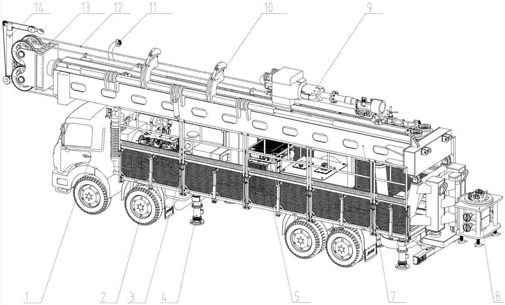
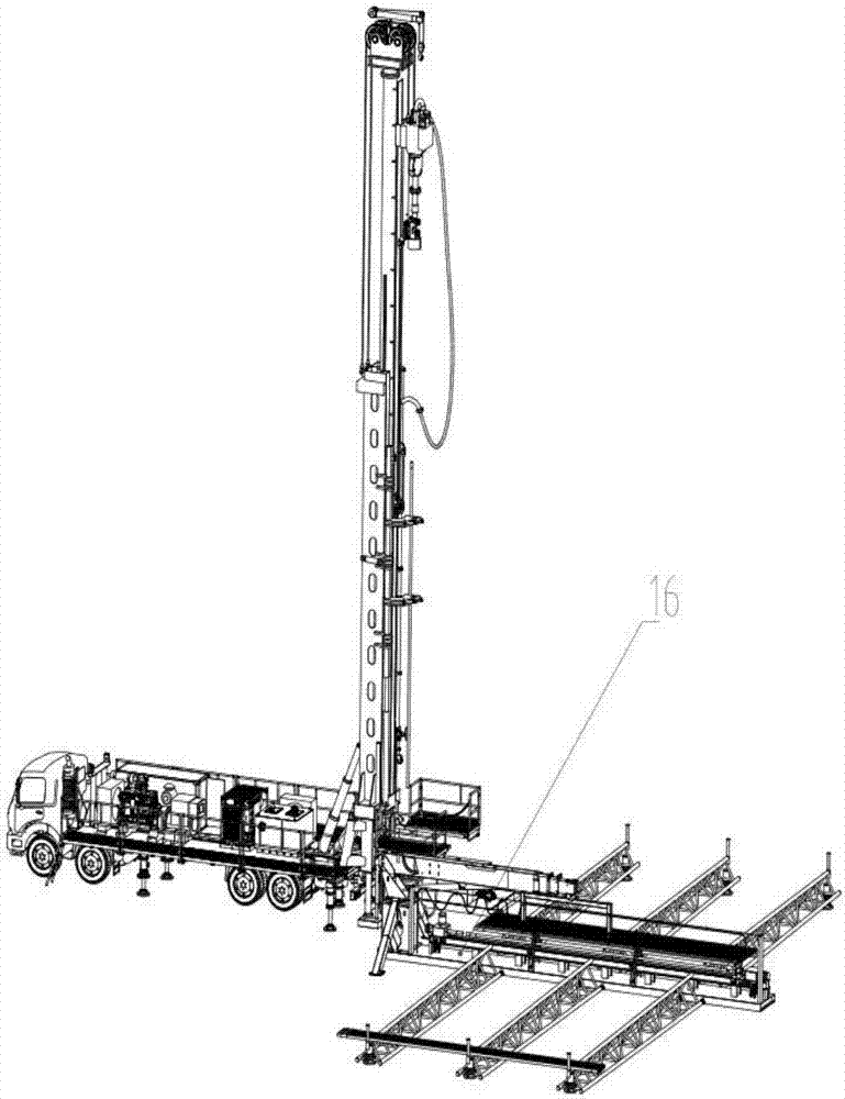
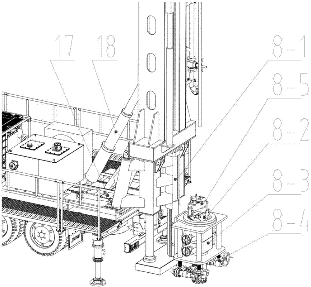
[0021] A fully automatic intelligent workover rig, including 1-chassis vehicle, 2-engine, 3-automatic turning walkway, 4-hydraulic adjustment leg, 5-hydraulic station, 7-luffing derrick, 8-wellhead device, 9 -Workover top drive, 10-Pipe grasping mechanism, 11-High pressure manifold, 12-Guiding wire rope, 13-Crown block, 14-Rotary hydraulic lifting small winch, 16-Tubing string automatic discharge device, 17-Derrick moving fast Positioning device, 18-Lifting cylinder, 19-Derrick support seat, 3-1. Guardrail assembly, 3-2. Walkway assembly, 3-3. Overturning tie rod assembly, 3-4 Overturning cylinder assembly, 8-1 Lifting adjustment device, 8-2 Automatic slips, 8-3 BOP, 8-4 Cross, 8-5 Oil pipe clamp, 16-1 Turning arm, 16-2, pick-up handle, 16-3 , Turnover mechanism, 16-4, oil pipe detection and maintenance device, 16-5, pipe rack, 16-6, pipe rack liquid cylinder.

[0022] The ...


PUM


Abstract

The invention belongs to the field of oil equipment, and particularly relates to a fully hydraulic intelligent workover rig. The fully hydraulic intelligent workover rig is characterized in that an engine 2 and a hydraulic pressure station 5 are installed on a chassis truck 1, in the conveying state, a walkway is folded automatically and stored, a wellhead assembly is fixed to the tail of the chassis truck, after the hydraulic workover rig is moved to a well site, a wellhead is subjected to initial positioning through a reverse image in a cab and positioning and ranging, and then accurate positioning is conducted by moving a rapid positioning device through a derrick; by conducting height adjusting and supporting on a vehicle carrying chassis through hydraulic adjusting landing legs and conducting mechanical locking, rapid positioning and locking of the wellhead are achieved; the automatic folding walkway is designed, and convenient and labor-saving installation is achieved; increasing and decreasing of pressure of a string in a well and setting and control of bit pressure and drilling speed parameters can be achieved automatically, full automatic operations such as tubing string gripping and conveying, automatic fastening and unfastening, automatic discharging and automatic detection are achieved; integrated transport of a blowout preventer is achieved, and separate disassembly and transport are not needed.

Description

technical field [0001] The invention belongs to the field of petroleum equipment, and in particular relates to a fully hydraulic intelligent workover rig, in particular to a kind of pressure-on-drill and pressure-on-drill of the pipe string intelligently mediating the workover operation according to the difference in the pressure in the well, which satisfies the lifting and lowering pressure of the tubing string. Rotating speed, prevent the liquid in the annulus in the well and the tubing string from blowing out, and at the same time realize the function of automatic transfer, row, pipe, make-up and break-out of the tubing string in the well site, and integrate the transportation of the blowout preventer and the automatic folding function of the walkway, which belongs to the technical field of petroleum equipment . Background technique [0002] In the traditional oilfield workover operations, the workover rig uses the drawworks to lift the hoisting system to realize the lift...

Claims


Application Information

Patent Timeline
IPC IPC(8): E21B19/00E21B19/086E21B19/14E21B19/16E21B19/18
CPCE21B19/00E21B19/086E21B19/14E21B19/16E21B19/18
Inventor 王树森刘士堂李心成刘海涛张炜张龙王庆朋李宏涛朱建建张君峰于岩岩
Owner YANTAI JEREH PETROLEUM EQUIP & TECH CO LTD
Learn More