Rapid optical imaging calculation method based on light source mutual intensity function decomposition

A technology of function decomposition and optical imaging, applied in optics, microlithography exposure equipment, optomechanical equipment, etc., can solve problems affecting the efficiency of lithography process design, affecting the efficiency of light intensity distribution calculation, time-consuming, etc., to meet the requirements of Lithography process design requirements, fast and efficient calculation, and the effect of reducing calculation steps

Inactive Publication Date: 2017-12-15
SUZHOU COGENDA ELECTRONICS CO LTD
View PDF0 Cites 7 Cited by
  • Summary
  • Abstract
  • Description
  • Claims
  • Application Information

AI Technical Summary

Problems solved by technology

However, according to the Hopkins optical imaging theory, a four-dimensional cross-transfer function TCC is established, and the calculation of the cross-transfer function TCC involves quadruple integral operations, which is very time-consuming
If the corresponding optical parameters change, TCC has to be recalculated, and the calculation of TCC according to the normal calculation method will seriously affect the efficiency of light intensity distribution calculation, thereby affecting the design efficiency of lithography process

Method used


Image

  • Rapid optical imaging calculation method based on light source mutual intensity function decomposition
  • Rapid optical imaging calculation method based on light source mutual intensity function decomposition
  • Rapid optical imaging calculation method based on light source mutual intensity function decomposition

Examples


Embodiment

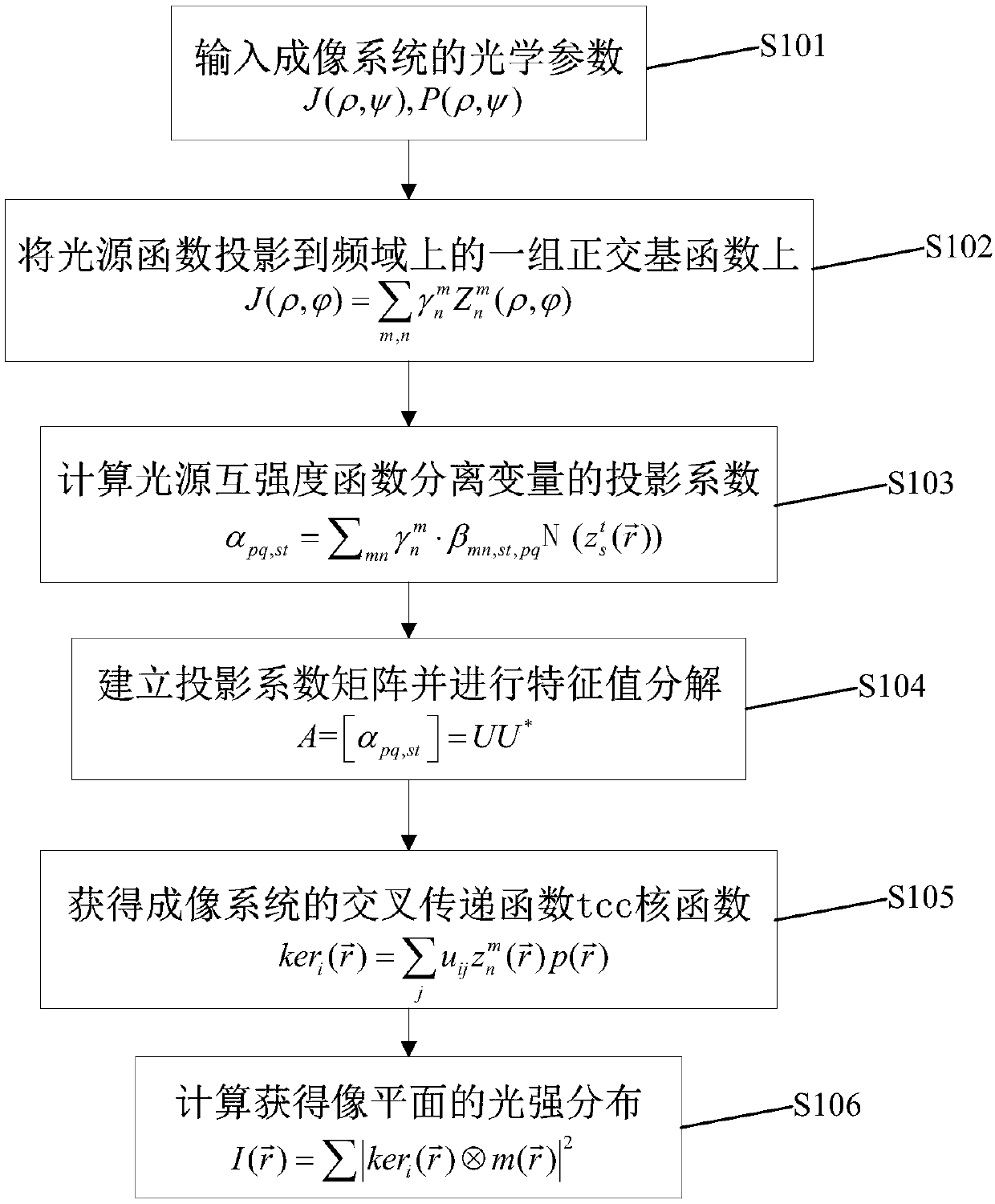
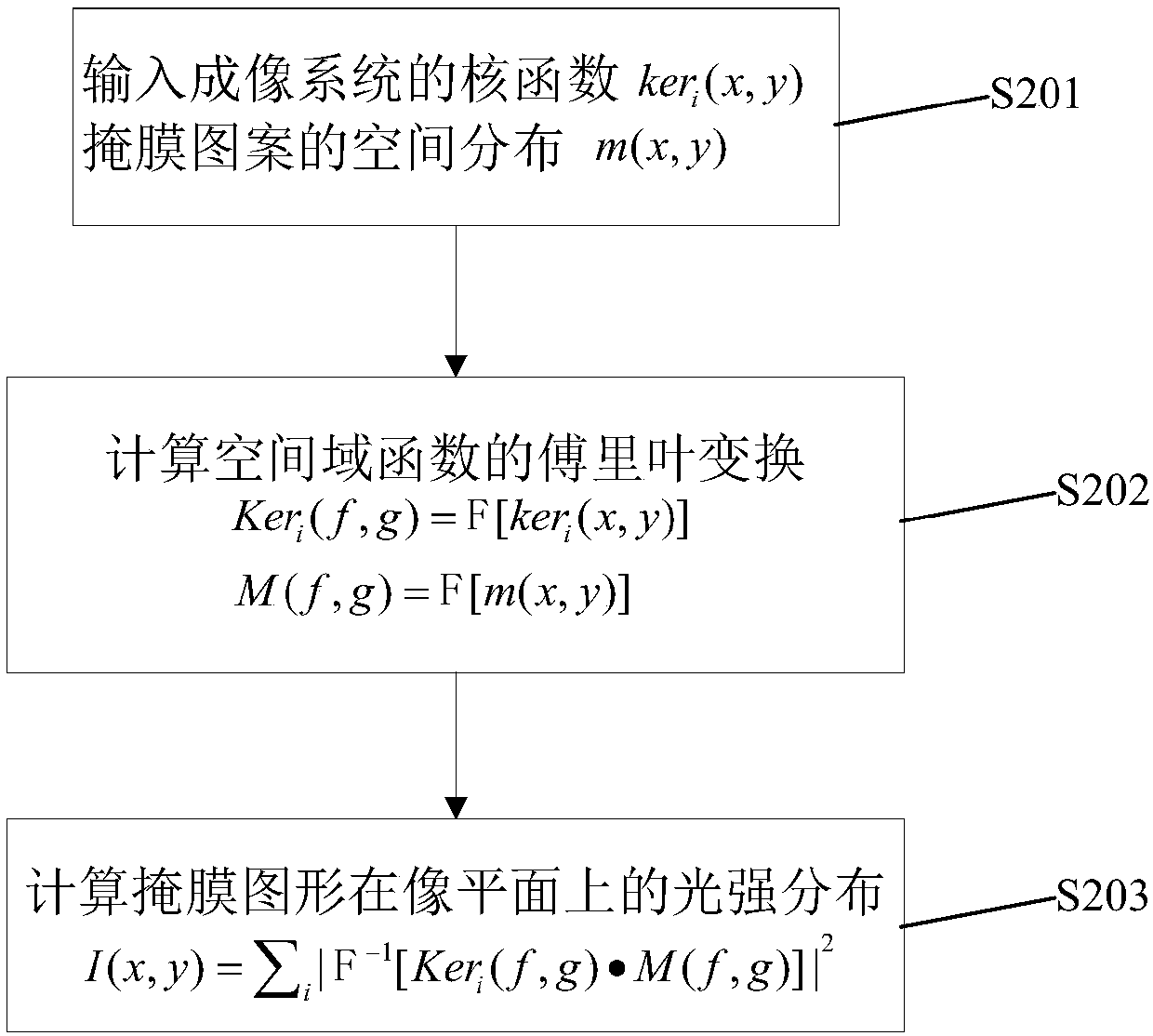
[0027] Based on the imaging theory of Hopkins diffractive optics, the formula of imaging light intensity distribution function is as follows:

[0028]

[0029] Among them, i is the imaginary number unit, M(f,g)=F[m(x,y)] is the two-dimensional Fourier transform (FFT, Fast Fourier Transform) of the spatial distribution of the mask plate, and TCC is the corresponding four-dimensional cross transfer function , which is defined as:

[0030] TCC(f 1 , g 1 ; f 2 , g 2 )=∫∫J(f,g)·P(f+f 1 ,g+g 1 )·P * (f+f 2 ,g+g 2 )dfdg (2)

[0031] Among them, J(f,g) is the light source function, P(f,g) is the pupil function of the imaging system, P * (f, g) is the complex conjugate of P(f, g) of the pupil function, expressing the optical parameters of the optical imaging system. According to Cobb's decomposition algorithm, there is a singular value decomposition of TCC as follows:

[0032]

[0033] Among them, Ker i (f, g) is the kernel function of TCC, then the light intensity d...


PUM


Abstract

The invention discloses a rapid optical imaging calculation method based on light source mutual intensity function decomposition. The rapid optical imaging calculation method comprises the following steps: 1) acquiring a light source function and a pupil function of an imaging system; 2) projecting the light source function to a group of orthogonal basis functions on a frequency domain; 3) solving a projection coefficient alpha pq,st of a base function corresponding to a light source mutual intensity function on a space domain; 4) establishing a positive definite projection matrix A=[alpha pq,st] by using the projection coefficient alpha pq,st, and performing feature vector decomposition A=UU*; 5) performing variables separation on the light source mutual intensity function, and establishing a kernel function of a cross transmission function on the space domain; and 6) calculating the convolution of the kernel function and a mask plate pattern, and acquiring an exposure pattern on an image plane. By adopting the method, Fourier function conversion pairs on a group of space domains and frequency domains are utilized, complex integral transformation is calculated according to convolution definition, then corresponding kernel functions are rapidly acquired, light intensity distribution can be rapidly and efficiently calculated, and thus actual photolithography process design requirements can be met.

Description

【Technical field】 [0001] The invention belongs to the technical field of lithographic resolution enhancement in semiconductor device process simulation, and in particular relates to a fast calculation method for optical imaging based on the decomposition of light source mutual intensity functions. 【Background technique】 [0002] In the production process of semiconductor devices, photolithography is the main means of industrial production at present. The photolithography process is based on diffractive optics, which obtains a specific pattern of light intensity distribution on the imaging plane. With the development of semiconductor technology, the size of semiconductor devices is getting smaller and smaller. When the feature size is close to or even smaller than the wavelength of light used in the photolithography process, optical diffraction will cause the exposure pattern formed on the silicon wafer to differ from the mask used. Compared with the template graphics, there...

Claims


Application Information

Patent Timeline
Patent Type & Authority Applications(China)
IPC IPC(8): G03F7/20
CPCG03F7/705G03F7/70508
Inventor 贡顶沈忱崔绍春毛智彪
Owner SUZHOU COGENDA ELECTRONICS CO LTD
Why Eureka
Try Eureka