Shaft furnace air intake device and shaft furnace air intake method

A technology of air intake device and shaft furnace, which is applied to shaft furnaces, furnaces, furnace types and other directions, can solve the problems of reducing the utilization rate of the shaft furnace, difficult to spread, and difficult to manufacture, and achieves the improvement of gas utilization rate and production efficiency, The effect of reducing the fuel ratio and production cost, and improving the metallization rate of sponge iron

Pending Publication Date: 2017-12-22
BAOSTEEL ENG & TECH GRP +1
View PDF9 Cites 4 Cited by
  • Summary
  • Abstract
  • Description
  • Claims
  • Application Information

AI Technical Summary

Problems solved by technology

From the perspective of production practice, although the AGD pipeline has some effects on improving the gas distribution in the shaft furnace, there are still some problems and deficiencies: it is difficult to manufacture and the cost is high; it is longer and wider, accounting for 30% of the cross-sectional area of ​​the shaft furnace, The utilization rate of the shaft furnace is reduced; water cooling is required, which poses a safety risk and also affects the temperature distribution in the furnace; the flow and temperature of the reducing gas entering the central area of ​​the shaft furnace through the AGD pipeline cannot be individually controlled, making it difficult to meet production needs
The device and method have the following problems and defects: the small holes on the side wall of the gas distribution device and the top of the cone are in direct contact with the charge used in production, the charge is tightly covered around the small hole, and the reduced ga

Method used


Image

  • Shaft furnace air intake device and shaft furnace air intake method
  • Shaft furnace air intake device and shaft furnace air intake method
  • Shaft furnace air intake device and shaft furnace air intake method

Examples


Embodiment Construction

[0035] The specific embodiments of the present invention are given below in conjunction with the accompanying drawings, but the present invention is not limited to the following embodiments. Advantages and features of the present invention will be apparent from the following description and claims. It should be noted that all the drawings are in very simplified form and use imprecise ratios, which are only used for the purpose of conveniently and clearly assisting in describing the embodiments of the present invention.

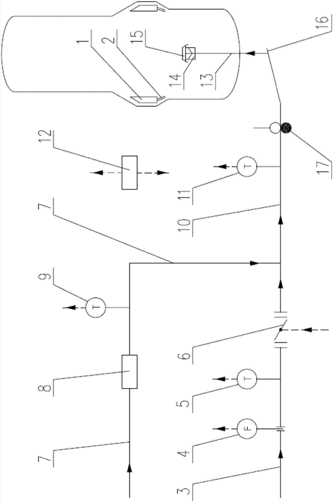
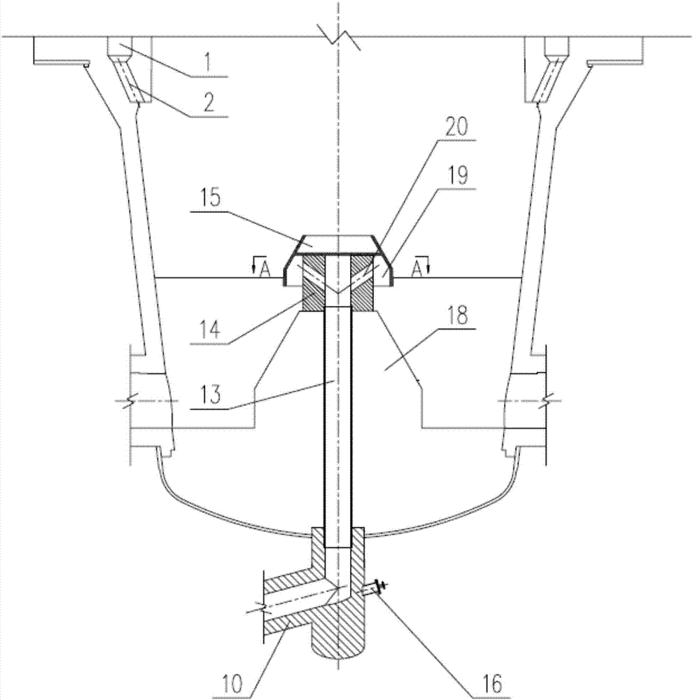
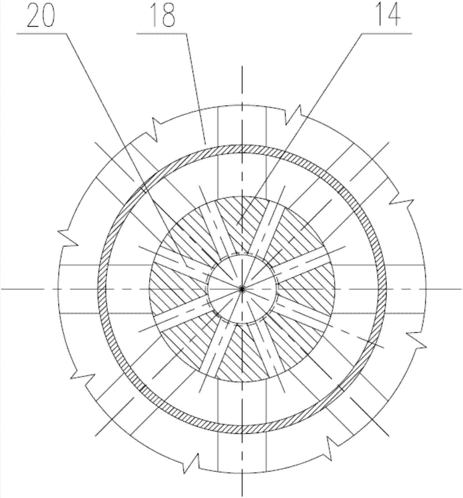
[0036] Please refer to figure 1 , figure 1Shown is a schematic structural view of the shaft furnace air intake device in the first preferred embodiment of the present invention. The invention proposes a shaft furnace air intake device, which includes a gas ring pipe 1 and a gas hole 2 from the middle of the shaft furnace. Control system, bottom air intake pipeline 13, gas distributor 14, protective cover 15, dust purging facility 16 and gas isolation facili...


PUM


Abstract

The invention provides a shaft furnace air intake device and a shaft furnace air intake method. The device comprises a gas circular pipe, a gas hole, a reduced gas conveying and processing system, a detecting and control system, a bottom air intake pipeline, a gas distributor, a protective cover, a dust blowing facility and a gas separation facility, wherein the gas circular pipe and the gas hole allow air to enter from the middle of a shaft furnace. The reduced gas conveying and processing system comprises a cold gas pipeline, a hot gas pipeline, a hot gas dust collector and a mixed gas pipeline. The detecting and control system comprises a cold gas thermometer, a cold gas flowmeter, a cold gas flow adjusting valve, a hot gas thermometer, a mixed gas thermometer and relevant control systems. According to the shaft furnace air intake device and the shaft furnace air intake method, the reduced gas is conveyed into the central area of the shaft furnace reliably and efficiently, the flow and temperature of the reduced gas are controlled independently according to practical production demands, so that the gas flow in the shaft furnace is evenly distributed, the temperature fields are reasonably distributed, accordingly the metallization ratio of sponge iron is increased, the gas utilization rate of the shaft furnace and the production efficiency are improved, and the fuel ratio of the shaft furnace and the production cost are lowered.

Description

technical field [0001] The invention relates to a shaft furnace used for non-blast furnace ironmaking, and in particular to a shaft furnace intake device and a method for realizing shaft furnace intake by using the shaft furnace intake device. Background technique [0002] For shaft furnaces commonly used in non-blast furnace ironmaking, such as Midrex shaft furnace, HYL shaft furnace, and Corex shaft furnace, the reducing gas passes through the gas ring pipe arranged in the middle of the shaft furnace and the gas holes connected to it and uniformly distributed along the shaft furnace circumferential direction. into the shaft furnace. With the increase of the diameter of the shaft furnace, it is difficult for the reducing gas to reach the central area of ​​the shaft furnace from the peripheral area of ​​the shaft furnace, and the distribution of the gas in the cross section of the shaft furnace is uneven, resulting in a lower metallization rate of sponge iron in the central ...

Claims


Application Information

Patent Timeline
IPC IPC(8): C21B13/02C21B11/02
CPCC21B11/02C21B13/0073C21B13/02
Inventor 吕遐平邹庆峰袁万能宋华冯华堂田果刘冬梅田宝山
Owner BAOSTEEL ENG & TECH GRP
Why Eureka
Try Eureka