Heat-pipe thermoelectric power generation energy storage and power transmission system for rear smoke channel of boiler

A thermoelectric power generation, tail flue technology, applied in generators/motors, electrical components, indirect heat exchangers, etc., can solve the problems of heating surface wear, low heat utilization rate of thermoelectric power generation, etc., to achieve strong anti-wear ability, use The effect of flexibility and improved heat transfer efficiency

Inactive Publication Date: 2017-12-29
SHANGHAI UNIVERSITY OF ELECTRIC POWER
View PDF5 Cites 17 Cited by
  • Summary
  • Abstract
  • Description
  • Claims
  • Application Information

AI Technical Summary

Problems solved by technology

[0006] The present invention aims at the low heat utilization rate of thermoelectric power generation by using the flue at the tail of the boiler, and proposes a heat pipe type thermoelectric power storage and power transmission system applied to the flue at the tail of the boiler. Utilization rate, and solve the problem of serious wear of the heating surface when this technology is applied to the tail flue of coal-fired boilers and other flue gases containing a large amount of solid particles such as dust.

Method used


Image

  • Heat-pipe thermoelectric power generation energy storage and power transmission system for rear smoke channel of boiler
  • Heat-pipe thermoelectric power generation energy storage and power transmission system for rear smoke channel of boiler
  • Heat-pipe thermoelectric power generation energy storage and power transmission system for rear smoke channel of boiler

Examples


Embodiment Construction

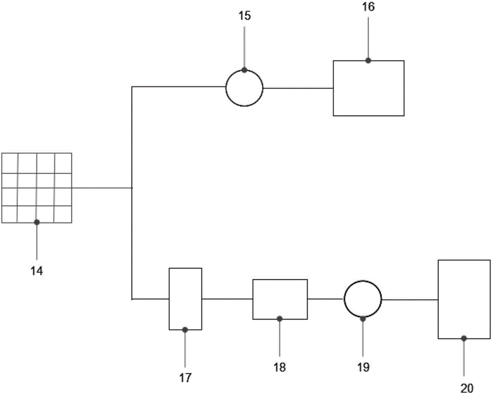
[0020] Such as figure 1 Shown is a schematic structural diagram of a heat pipe thermoelectric power generation energy storage and power transmission system applied to the tail flue of a boiler. The system includes a thermoelectric power generation system 14, a power supply system and an energy storage system. The thermoelectric power generation system 14 includes multiple thermoelectric power generation units. The thermoelectric power generation units are embedded in the tail flue. The hot end heat pipe device of the thermoelectric power generation unit is in contact with the high-temperature flue gas, and the cold end heat pipe device is in contact with the ambient air. The power supply system sequentially includes an inverter 17 , a power transmission stabilizer protector 18 , a power transmission meter 19 and an electrical consumer 20 . The energy storage system includes a power storage meter 15 and a power storage device 16 in sequence.

[0021] When the system supplies p...


PUM


Abstract

The invention relates to a heat-pipe thermoelectric power generation energy storage and power transmission system for a rear smoke channel of a boiler, and the system comprises a thermoelectric power generation system, an energy supply system, and an energy storage system. A thermoelectric power generation unit in the thermoelectric power generation system comprises a cold-end heat pipe device, a hot-end heat pipe device and a thermoelectric power generation piece disposed between the cold-end heat pipe device and the hot-end heat pipe device, wherein the cold-end heat pipe device and the hot-end heat pipe device are vertically arranged in a structure. The thermoelectric power generation piece is disposed on the rear smoke channel, and the hot-end heat pipe device of the thermoelectric power generation unit makes contact with the high-temperature flue gas to absorb heat, and maintains the high temperature of the hot surface of the thermoelectric power generation piece. The cold-end heat pipe device makes contact with the ambient atmosphere, and maintains the low temperature of a cold surface of the thermoelectric power generation piece. A direct current generated by the thermoelectric power generation system is converted and then is outputted to an electric appliance. Meanwhile, the redundant electric energy is directly stored in the energy storage device. Two ends of the thermoelectric power generation piece form a big temperature difference through the high-efficiency thermal conduction characteristics of a hot pipe, thereby improving the power generation efficiency of the thermoelectric power generation piece. The hot pipe is changed to be elliptical, thereby effectively reducing the wear, caused by solid particles, of the hot pipe.

Description

technical field [0001] The invention relates to a heat transfer and energy-saving technology, in particular to a heat pipe type thermoelectric power generation energy storage and power transmission system applied to the tail flue of a boiler. Background technique [0002] The flue gas produced by fuel combustion in power plant boilers, industrial boilers or gas boilers has a relatively high temperature. Power plant boilers generally use this part of heat by arranging the heating surface and then discharge it into the environment through the chimney, but there are still a lot of losses in this process, including heat loss, heat transfer loss and smoke exhaust loss. The exhaust smoke from industrial boilers is generally directly discharged into the environment, and it is rarely used, resulting in a large amount of energy waste. If the heat can be efficiently utilized for thermoelectric power generation, it will be an effective way to save energy. [0003] Thermoelectric powe...

Claims


Application Information

Patent Timeline
Patent Type & Authority Applications(China)
IPC IPC(8): H02N11/00F28D15/02
CPCH02N11/002F28D15/02
Inventor 秦岭尤运潘卫国汪腊珍姜未汀涂钊佘小利黄春迎张莉胡双清
Owner SHANGHAI UNIVERSITY OF ELECTRIC POWER
Why Eureka
Try Eureka