Light-emitting diode and method of making the same

A technology of light-emitting diodes and manufacturing methods, which is applied in the direction of semiconductor devices, electrical components, circuits, etc., can solve the problems of sacrificing the area of ​​the active area, increasing the cost of chip manufacturing, and current congestion, so as to improve the current blocking ability and improve the ohm Effect of contact ability and uniform distribution of current

Active Publication Date: 2019-04-19
XIAMEN CHANGELIGHT CO LTD
View PDF4 Cites 0 Cited by
  • Summary
  • Abstract
  • Description
  • Claims
  • Application Information

AI Technical Summary

Problems solved by technology

[0003] The current blue-green light-emitting diodes have the problem of current crowding, especially for high-power light-emitting diodes.
The inventors found that the reason for the current crowding is that the structure of blue-green light-emitting diodes is mostly epitaxial multi-layer gallium nitride-based material structure on a sapphire substrate, and the sapphire substrate is a non-conductive material, so the light-emitting diode formed The two electrodes are distributed horizontally, and the horizontally distributed electrodes are at the same level, which leads to current crowding, especially for high-power flip-chip LEDs. Due to the large driving current, current crowding is more likely to occur, resulting in a significant drop in saturation current. , resulting in a significant reduction in luminous efficacy
[0004] In the prior art, in order to improve the current crowding phenomenon, one solution is to design a complex electrode structure that cooperates with each other. Multiple isolation layers are used between the two electrodes to isolate the unnecessary contact between the electrode and the epitaxial material, but the complex electrode structure, It leads to complex manufacturing process, and also sacrifices the area of ​​the active area
Another solution is to adopt a vertical chip structure, but the substrate lift-off process and silicon substrate bonding process are required in the production process
Both of the above two solutions lead to an increase in the production cost of the chip and a decrease in the chip yield.

Method used


Image

  • Light-emitting diode and method of making the same
  • Light-emitting diode and method of making the same
  • Light-emitting diode and method of making the same

Examples


Embodiment Construction

[0054] The following will clearly and completely describe the technical solutions in the embodiments of the present invention with reference to the accompanying drawings in the embodiments of the present invention. Obviously, the described embodiments are only some, not all, embodiments of the present invention. Based on the embodiments of the present invention, all other embodiments obtained by persons of ordinary skill in the art without making creative efforts belong to the protection scope of the present invention.

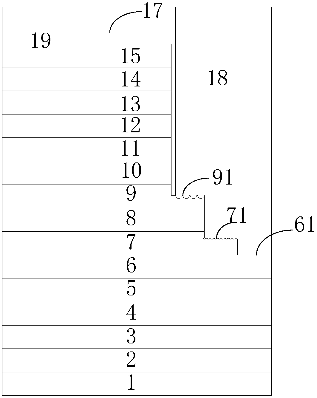
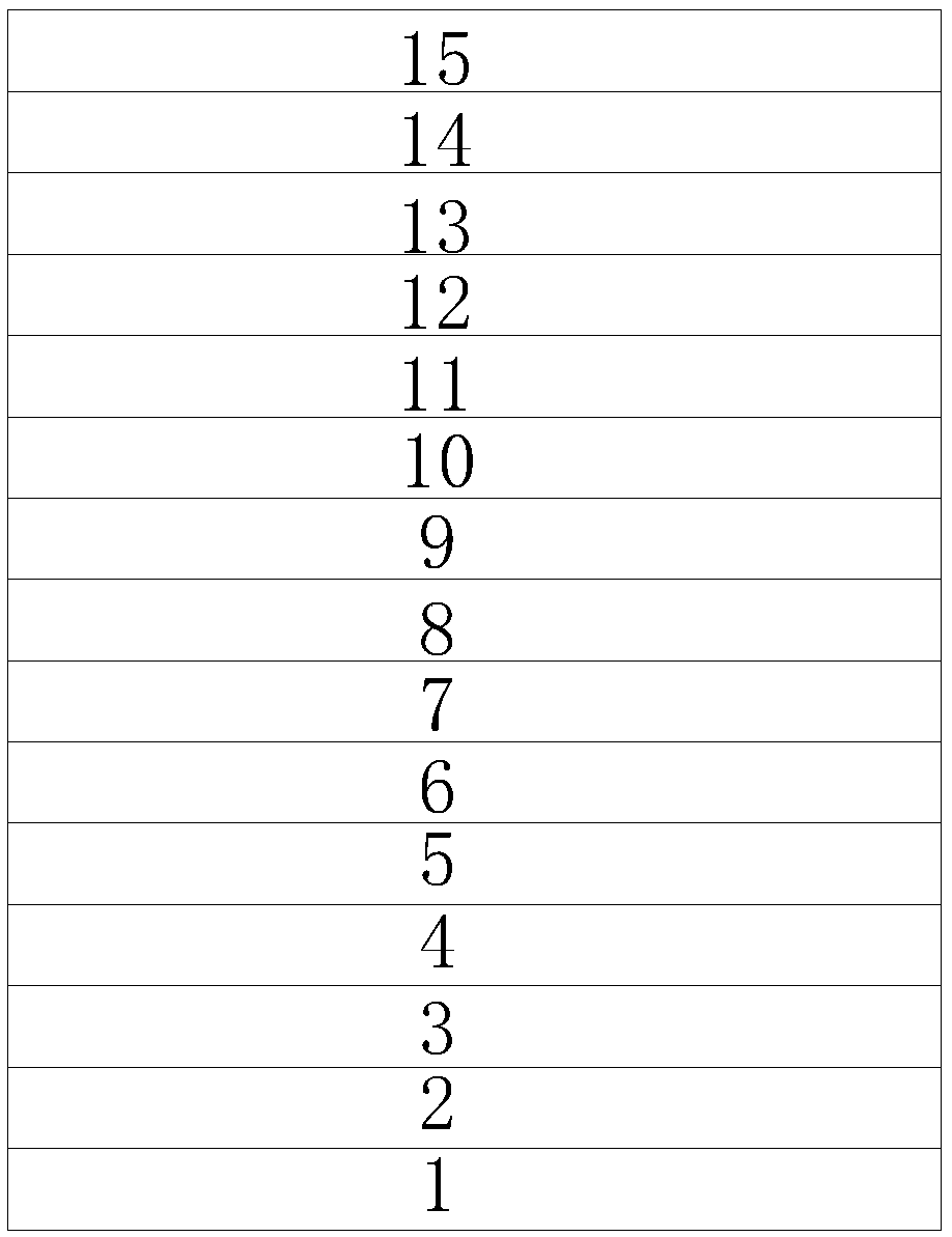
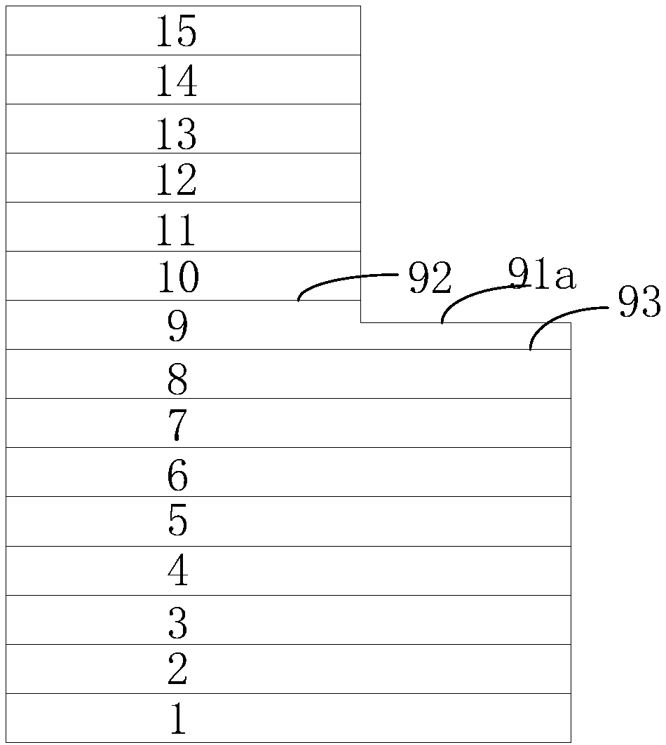
[0055] An embodiment of the present invention provides a light emitting diode, the structure of which is shown in figure 1 As shown, the light-emitting diode includes the following structure:

[0056] A substrate 1, and a buffer layer 2, an unintentionally doped layer 3, a first doped layer 4, a first heavily doped layer 5, a first ohmic contact layer 6, a first Highly doped layer 7, first isolation layer 8, second doped layer 9, first current blocking layer ...


PUM


Abstract

The invention discloses a light emitting diode (LED) and a manufacturing method thereof. The LED comprises a substrate, a buffer layer, an unintentional doping layer, a first doping layer, a first heavy doping layer, a first ohmic contact layer, a first high doping layer, a first isolation layer, a second doping layer, a first current blocking layer, an active region, a second current blocking layer, a third doping layer, a second ohmic contact layer, a transparent conductive layer, a first electrode, a second electrode and a third electrode, wherein the second doping layer comprises a first platform, the first high doping layer comprises a second platform, the first ohmic contact layer comprises a third platform, the first platform, the second platform and the third platform are differentin surface roughness, the first electrode directly contacts with the first platform, the second platform and the third platform, and the first electrode and the second electrode realize electrical isolation through a second protection layer. The LED is advantaged in that the manufacturing process is simple, manufacturing cost of chips is reduced, and a current congestion problem of the LED is effectively solved.

Description

technical field [0001] The present invention relates to light-emitting diodes, and more specifically, to a light-emitting diode and a manufacturing method thereof. Background technique [0002] A light emitting diode (Light Emitting Diode, LED) is an optoelectronic semiconductor element that can convert current into a specific wavelength range. It has the advantages of low power consumption, small size, high brightness, easy matching with integrated circuits, and high reliability, and is widely used as a light source. [0003] Current blue-green light-emitting diodes have the problem of current crowding, especially for high-power light-emitting diodes, which causes a significant drop in saturation current to a large extent, thereby reducing light efficiency. The inventors found that the reason for the current crowding is that the structure of blue-green light-emitting diodes is mostly epitaxial multi-layer gallium nitride-based material structure on a sapphire substrate, an...

Claims


Application Information

Patent Timeline
Patent Type & Authority Patents(China)
IPC IPC(8): H01L33/14H01L33/22
Inventor 林志伟陈凯轩李俊贤卓祥景汪洋
Owner XIAMEN CHANGELIGHT CO LTD
Why Eureka
Try Eureka