Multilevel inverter power supply for electromagnetic stirring and control method for multilevel inverter power supply

A multi-level inverter and electromagnetic stirring technology, which is applied to electrical components, AC power input to DC power output, output power conversion devices, etc., can solve the problem of power thyristor system stability reduction, three-arm inverter power supply Complex structure, large number of switching devices, etc., to improve the characteristics of suppressing electromagnetic interference, increase system stability, and reduce production costs

Inactive Publication Date: 2018-01-05
HUNAN UNIV
View PDF3 Cites 4 Cited by
  • Summary
  • Abstract
  • Description
  • Claims
  • Application Information

AI Technical Summary

Problems solved by technology

However, the current electromagnetic stirring power supply generally uses a conventional voltage source three-leg inverter main circuit, which has a large volume and the output voltage frequency is the same as the IGBT switching frequency. If you want to output high-frequency voltage, you must greatly increase The switching frequency of IGBT not only has switching loss, but also easily leads to the generation of switching noise and large torque vibration
At the same time, the structure of the three-arm inverter power supply is complex, the number of switching devices is large, and the production cost is high. The increase in the number of power thyristors also reduces the stability of the system and easily causes safety hazards.
At the same time, using the previous inverter power supply, in order to achieve a better steelmaking effect, the asymmetric winding motor is often used, which greatly reduces the usable range.

Method used


Image

  • Multilevel inverter power supply for electromagnetic stirring and control method for multilevel inverter power supply
  • Multilevel inverter power supply for electromagnetic stirring and control method for multilevel inverter power supply
  • Multilevel inverter power supply for electromagnetic stirring and control method for multilevel inverter power supply

Examples


Embodiment Construction

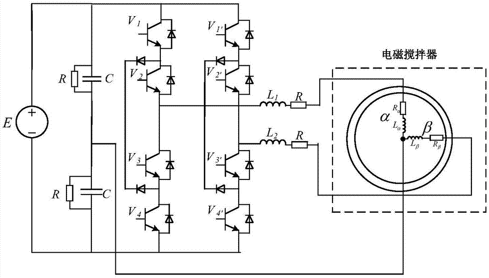
[0017] like figure 1 As shown, the present invention clamps the multi-level H-bridge inverter input terminal to be connected with two capacitors, is connected in parallel with a voltage equalizing resistor to balance the capacitor voltage, and supplies power to the capacitor from a DC stabilized voltage source; the inverter end is composed of 8 IGBTs and It is composed of diodes connected in antiparallel; 8 IGBTs are divided into two groups, and each group is connected in series with four IGBTs to form the left bridge arm and the right bridge arm. The center point of each bridge arm is connected to the head end of the induction coil of the motor. The left and right bridge arms are independent of each other, outputting an orthogonal current, which is filtered by the inductance to supply power to the induction coil; the ends of the two coil windings of the motor are connected together to the central tap of the capacitor.

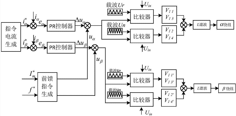
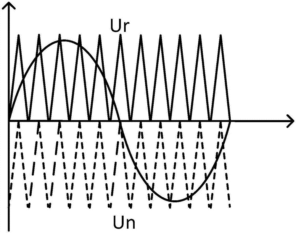
[0018] Control method of the present invention comprises...


PUM


Abstract

The invention discloses a multilevel inverter power supply for electromagnetic stirring and a control method for the multilevel inverter power supply. A high-voltage DC power supply is connected to aninput end of a clamping inverter power supply, and DC capacitor voltage is balanced by grading resistors. DC voltage outputs multilevel step waves through an inverter. A compound control system of current feedback control and feedforward control is adopted for an inverter side, on-off control is carried out on IGBTs of the inverter side, a left bridge arm and a right bridge arm output AC of whichthe phase difference is 90 degrees and electromagnetic thrust is formed through excitation, so that molten steel carries out rotational motion. A clamping multilevel H-bridge inverter module is adopted, so that compared with a traditional inverter power supply adopted for electromagnetic stirring, the multilevel inverter power supply has the advantages of being simple in structure, high in stability and low in production cost; and by adopting a multilevel technology, the equivalent switching frequency of a switching device is increased, the loss is reduced and the power quality of output current is improved.

Description

technical field [0001] The invention relates to a power supply for rotating magnetic field type electromagnetic stirring, in particular to a multi-level inverter power supply for electromagnetic stirring and a control method thereof. Background technique [0002] Electromagnetic stirring technology is beneficial to remove gas and inclusions in metal solution, and is an effective means to improve metal solidification structure and improve the quality of metal products. When the current-carrying molten steel is in the alternating magnetic field, a current will be induced in the molten steel, and the induced current will generate an electromagnetic force in the magnetic field to push the molten steel to move. [0003] In general, what the electromagnetic stirrer needs is a low-frequency, large-value sinusoidal alternating current. Changing the frequency and amplitude of the current can change the frequency and intensity of stirring. This stirring method has the energy concentra...

Claims


Application Information

Patent Timeline
Patent Type & Authority Applications(China)
IPC IPC(8): H02M7/487
Inventor 罗安王逸兴徐千鸣岳雨霏郭鹏丁红旗洪乐荣周芊帆
Owner HUNAN UNIV
Why Eureka
Try Eureka