

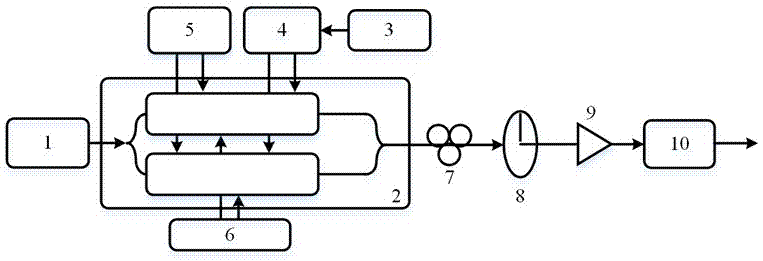
Optical generation device and method for phase coding signal with tunable multiplication factor
A phase-encoded signal and generation device technology, applied in electrical components, electromagnetic wave transmission systems, transmission systems, etc., can solve problems such as high complexity and implementation cost, limited signal time length, and limited use range, and achieve low implementation costs. , reduced bandwidth requirements, the effect of a large frequency tunable range
- Summary
- Abstract
- Description
- Claims
- Application Information
AI Technical Summary
Problems solved by technology
Method used
Image

Examples
Embodiment 1
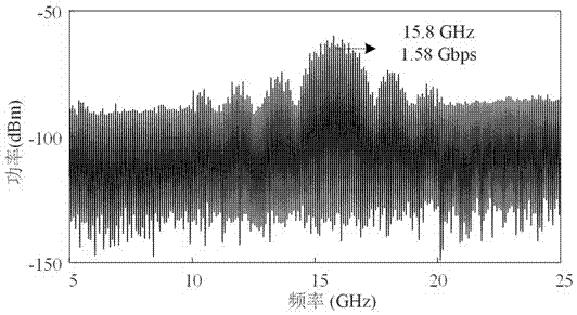
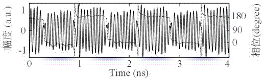
[0079]In this embodiment, the wavelength of the laser is 1550.55nm, and the microwave signal generator generates a microwave signal of 15.8GHz, and adjusts the DC bias voltage so that the sub-MZM of the input coded signal in the sub-DP-MZM1 is biased at the minimum transmission point, and the input microwave signal The sub-MZM is biased at the minimum transmission point; the sub-MZM of the input encoded signal in the sub-DP-MZM2 is biased at the minimum transmission point, and the sub-MZM of the input microwave signal is biased at the maximum transmission point; the main MZM of the sub-DP-MZM1 is The bias is at the maximum transmission point, and the main MZM of the sub-DP-MZM2 is biased at the orthogonal transmission point; adjust the polarization controller so that the angle between a polarization axis of the DP-QPSK modulator and the polarizer axis is 45°. When the encoded signal is a binary pseudo-random sequence of 1.58Gbps, the spectrum of the fundamental frequency binary...
Embodiment 2
[0081] In this embodiment, the wavelength of the laser is 1550.55nm, and the microwave signal generator generates a microwave signal of 7.9GHz, and adjusts the DC bias voltage so that the sub-MZM of the input coded signal in the sub-DP-MZM1 is biased at the minimum transmission point, and the input microwave signal The sub-MZM is biased at the minimum transmission point; the sub-MZM of the input encoded signal in the sub-DP-MZM2 is biased at the minimum transmission point, and the sub-MZM of the input microwave signal is biased at the maximum transmission point; the main MZM of the sub-DP-MZM1 is The bias is at the orthogonal transmission point, and the main MZM of the sub-DP-MZM2 is biased at the maximum transmission point; adjust the polarization controller so that the angle between one polarization axis of the DP-QPSK modulator and the polarizer axis is 45°. When the encoded signal is a binary pseudo-random sequence of 1Gbps, the spectrum of the binary phase encoded signal o...
Embodiment 3
[0083] In this embodiment, the wavelength of the laser is 1550.55nm, and the microwave signal generator generates a microwave signal of 5.3GHz, and adjusts the DC bias voltage so that the sub-MZM of the input coded signal in the sub-DP-MZM1 is biased at the minimum transmission point, and the input microwave signal The sub-MZM is biased at the minimum transmission point; the sub-MZM of the input encoded signal in the sub-DP-MZM2 is biased at the minimum transmission point, and the sub-MZM of the input microwave signal is biased at the maximum transmission point; the main MZM of the sub-DP-MZM1 is The bias is at the maximum transmission point, and the main MZM of the sub-DP-MZM2 is biased at the orthogonal transmission point; adjust the polarization controller so that the angle between the main axis of polarization of the DP-QPSK modulator and the axis of the polarizer is 45°, which is amplified by the electric amplifier , so that J 1 (κ)=0 holds true. When the encoded signal ...
PUM
 Abstract
Description
Claims
Application Information