
Air suction system of laser cutting machine and laser cutting machine

A laser cutting machine, laser cutting technology, applied in laser welding equipment, welding equipment, metal processing equipment and other directions, can solve the problems of working environment pollution, low cutting quality, easy deviation of plates, etc., to ensure quality and prevent plates deformation effect

Pending Publication Date: 2018-01-09
河南艾顿机床有限公司
View PDF0 Cites 11 Cited by
  • Summary
  • Abstract
  • Description
  • Claims
  • Application Information

AI Technical Summary

Problems solved by technology

[0004] One of the purposes of the embodiments of the present invention is to provide a suction system for a laser cutting machine, which aims to solve the problems in the above-mentioned prior art that the plates to be cut are easily shifted, resulting in poor cutting quality and smoke and dust generated during the cutting process. Chips and welding slag lead to problems such as pollution of the working environment

Method used


Image

  • Air suction system of laser cutting machine and laser cutting machine
  • Air suction system of laser cutting machine and laser cutting machine
  • Air suction system of laser cutting machine and laser cutting machine

Examples


Embodiment

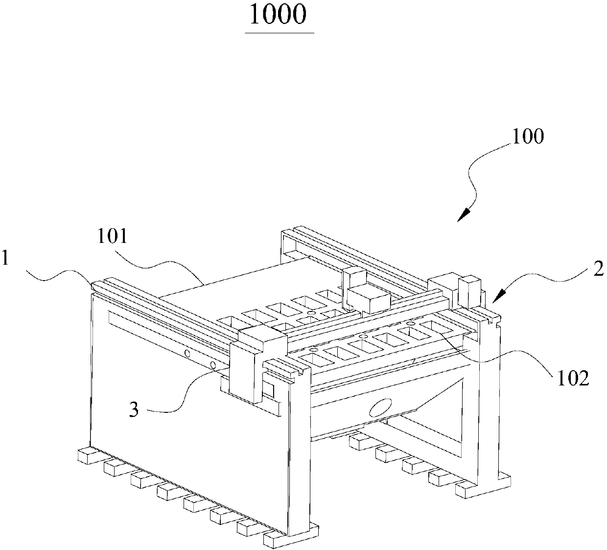
[0042] Please refer to figure 1 , figure 1The specific structure of a laser cutting machine 1000 provided in this embodiment is shown, and the laser cutting machine 1000 is used for the workbench 1 of laser cutting plates; wherein the workbench 1 is provided with a suction system 100 of the laser cutting machine 1000, The suction system 100 includes a suction structure 2 and a moving assembly 3, the purpose of which is not only to smoothly absorb the cut material on the workbench 1, but also to suck the waste gas generated during cutting.

[0043] The laser cutting machine 1000 includes a workbench 1 for laser cutting plates, a moving assembly 3 arranged above the workbench 1, and a suction structure 2 arranged below the workbench 1; Located on both sides of the workbench 1, the moving assembly 3 is provided with a laser cutting head 4; the air suction structure 2 is connected with the moving assembly 3, and is used for synchronous air suction as the moving assembly 3 moves. ...


PUM


Abstract

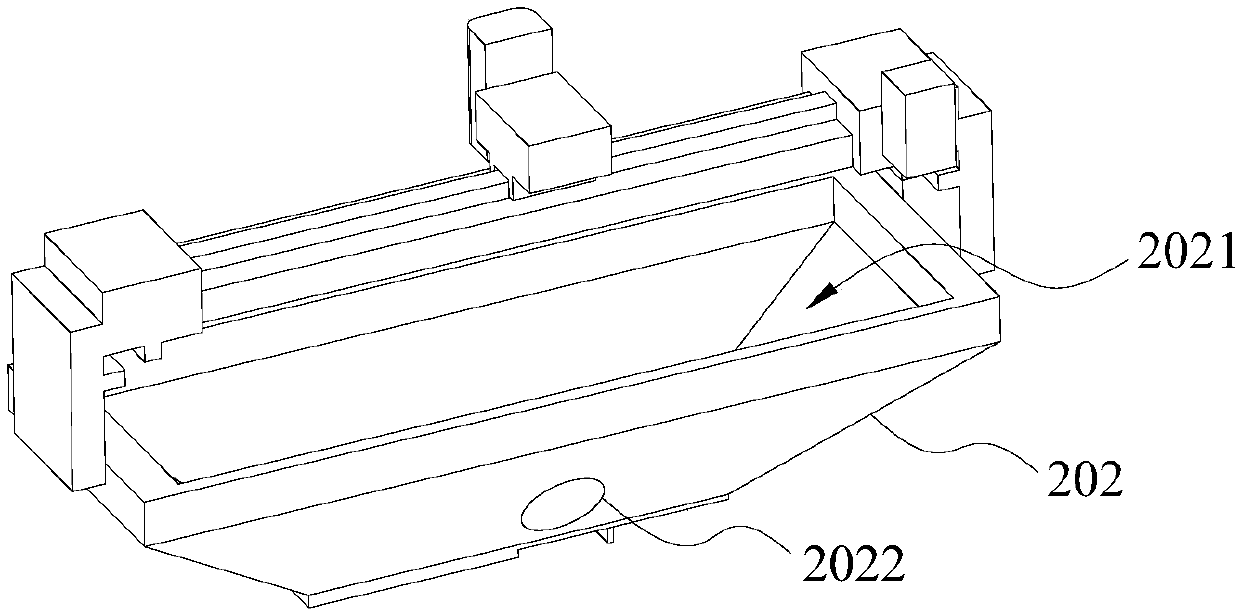
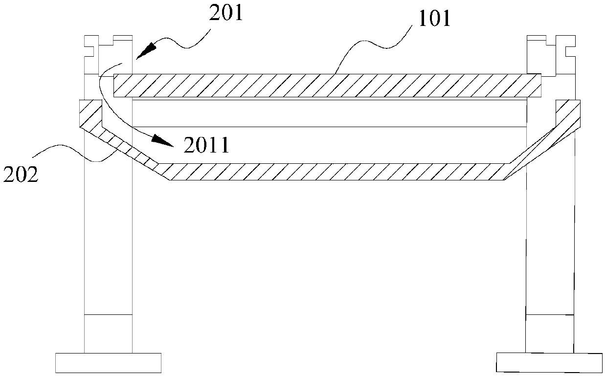
The invention discloses an air suction system of a laser cutting machine and the laser cutting machine, and relates to the technical field of laser machining equipment. The air suction system comprises an air suction structure and a movable assembly, wherein the air suction structure comprises air suction holes and an air suction box; the air suction holes are located in the two sides of a workbench in the width direction and used for adsorbing waste gas and impurities such as dust produced during cutting; the air suction box located on the lower end face of the workbench is provided with an air suction cavity connected with an external suction fan; and a metal plate located on the upper end face of the workbench is stably adsorbed to the workbench through negative pressure generated by the air suction cavity, thus, the to-be-cut plate can be prevented from being deformed through internal stress springback, the cutting accuracy is improved, and the percent of pass of cut plates is ensured.

Description

technical field [0001] The invention relates to the technical field of laser processing equipment, in particular to a suction system of a laser cutting machine and the laser cutting machine. Background technique [0002] The laser cutting machine is to focus the laser beam emitted from the laser device into a laser beam with high power density through the optical path system. The laser beam irradiates the surface of the workpiece to make the workpiece reach the melting or boiling point. At the same time, the high-pressure gas coaxial with the beam will blow away the melted or vaporized metal. As the relative position of the beam and the workpiece moves, the material will eventually form a slit, thereby achieve the purpose of cutting. [0003] When laser cutting metal sheet and other parts, the sheet is easy to shift with the movement of the laser head without any fixation, resulting in low cutting quality. Not only that, when cutting metal, smoke, debris and welding slag w...

Claims


Application Information

Patent Timeline
IPC IPC(8): B23K26/38B23K26/70B23K26/16
Inventor 孙敬伟
Owner 河南艾顿机床有限公司
Learn More