Annular-spraying electrostatic spinning machine and application

A technology of electrospinning and ring spraying, which is applied in the direction of yarn, textiles, papermaking, fiber processing, etc. It can solve the problems of incompetence in diversified production, difficulty in real-time adjustment, inconvenient replacement of machine heads, etc., to facilitate mass production, Guarantee the effect of normal spinning and simple structure

Inactive Publication Date: 2018-01-09
SHANGHAI UNIV OF ENG SCI
View PDF8 Cites 5 Cited by
  • Summary
  • Abstract
  • Description
  • Claims
  • Application Information

AI Technical Summary

Problems solved by technology

However, because different polymers need to use different nozzles, the existing multi-nozzle electrospinning equipment is inconvenient to replace the nozzles, and it is also difficult to adjust in real time during mass production, which cannot meet the needs of diversified production

Method used


Image

  • Annular-spraying electrostatic spinning machine and application
  • Annular-spraying electrostatic spinning machine and application
  • Annular-spraying electrostatic spinning machine and application

Examples


Embodiment 1

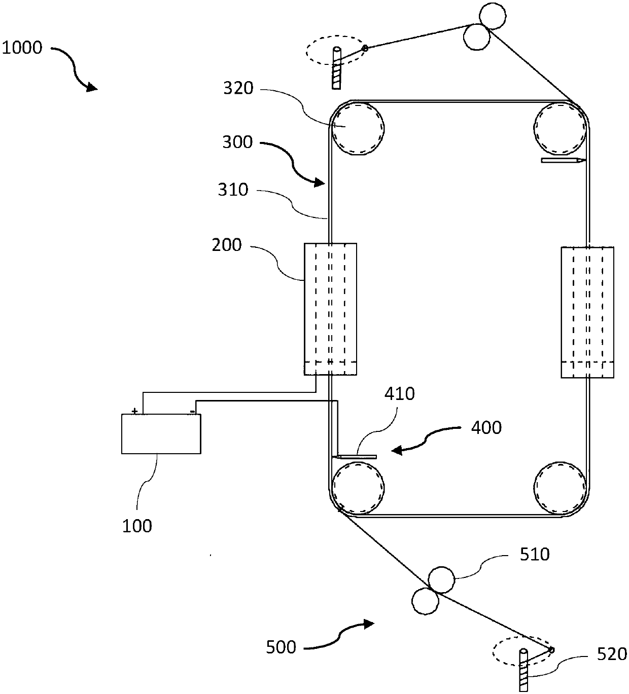
[0031] figure 1 It is a structural schematic diagram of the ring-jet electrostatic spinning machine in the embodiment of the present invention.

[0032] Such as figure 1 As shown, a ring-jet electrospinning machine 1000 includes a high-voltage DC power supply 100 , m spinning devices 200 , a spinning receiver 300 , a stripping device 400 and a traction and twisting device 500 . Wherein, m is a natural number greater than or equal to 1, and two spinning devices 200 are used in this embodiment.

[0033] The high-voltage DC power supply 100 is a high-voltage electrostatic generator, which has a positive pole and a negative pole, and is used to generate a high-voltage electrostatic field.

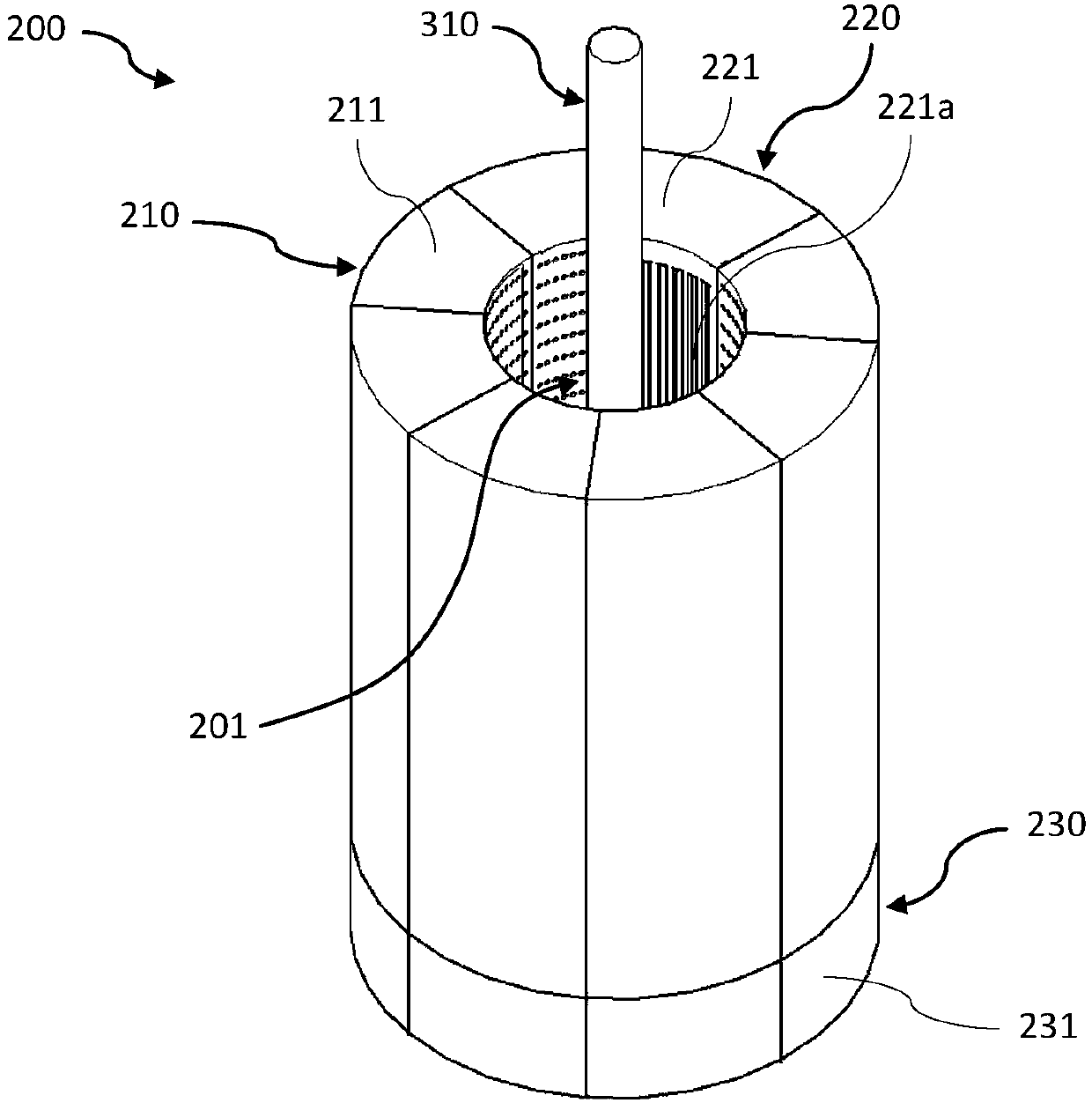
[0034] figure 2 It is a schematic diagram of the three-dimensional structure of the spinning device in the embodiment of the present invention;

[0035] Such as figure 2 As shown, the spinning device 200 is used to spin the spinning solution to form fibers, including a fixed bracket (not...

Embodiment 2

[0062] The second embodiment is a further improvement of the first embodiment, and the same structures as those in the first embodiment are given the same symbols and the same descriptions are omitted.

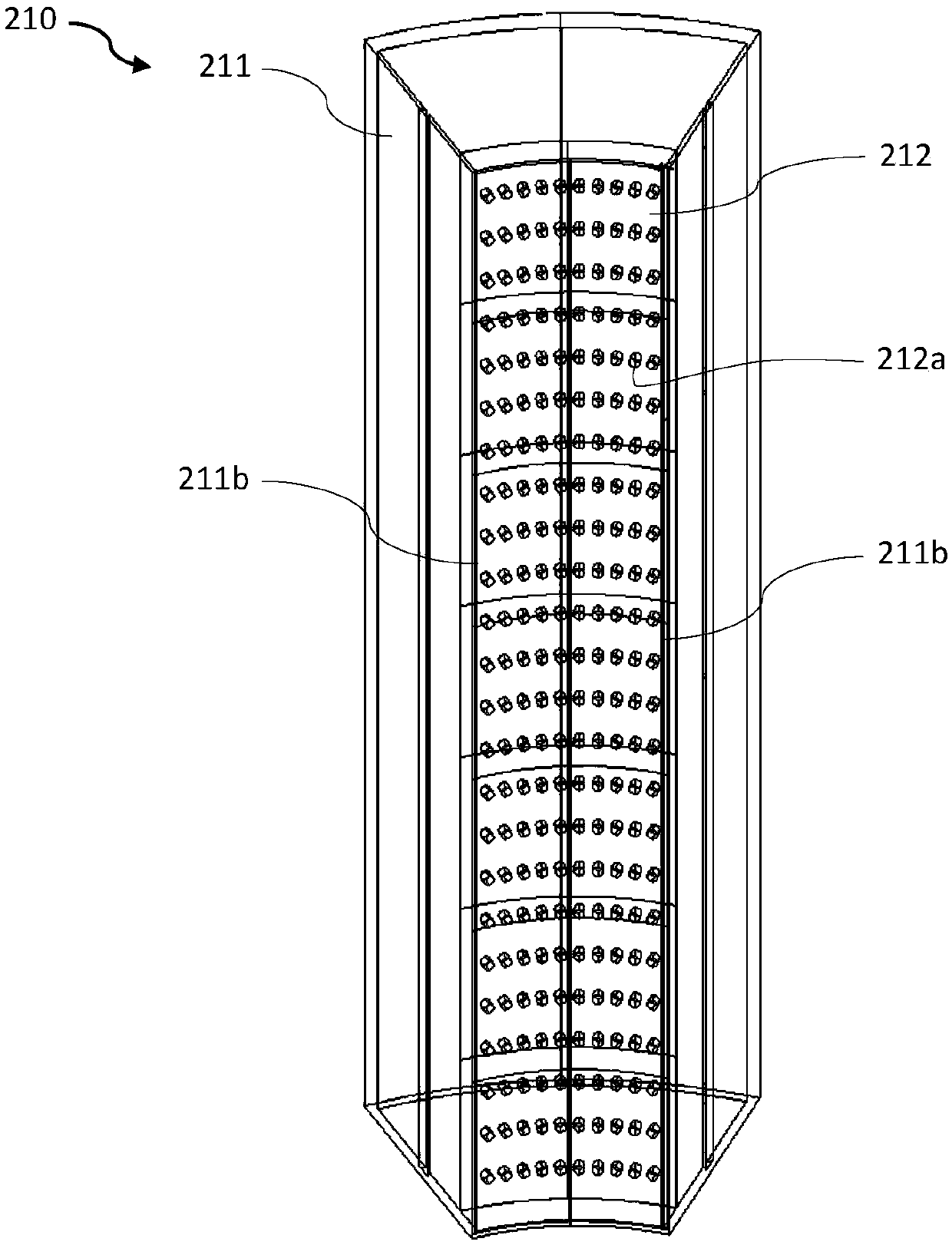
[0063] Such as image 3 As shown, the spinneret 212 moves up and down along the spinneret box 211 to make the spinneret 212a and the liquid outlet hole 211a match or stagger. The specific structure is: the left and right sides of the spinneret 212 are provided with There is a buckle (not shown in the figure), and the side of the spin box 211 close to the hollow cavity 201 is provided with a vertical groove 211b matching the buckle, and the spinneret 212 is movably inserted in the buckle by the buckle. The corresponding vertical slot 211b is installed on the spinner box 211 and can move up and down along the spinner box 211 .

[0064] The end of each spinneret box 211 is correspondingly provided with a spinneret driving part for driving the spinneret 212 to move up and down al...

Embodiment 3

[0067] Embodiment 3 is a further improvement of Embodiment 1 and Embodiment 2. For the same structures as those in Embodiment 1 and Embodiment 2, the same symbols are given and the same descriptions are omitted.

[0068] In this embodiment, the liquid injection unit in Embodiment 1 is omitted, and the spinneret box 211 adopts an ink cartridge structure that repeatedly adds liquid, and has its own pressurization unit. The specific structure is as follows:

[0069] Such as Figure 4 As shown, the spinner box 211 is provided with a vertical partition 214c, which divides the inner space of the spinner box 211 into a spinneret chamber 211d and a pressurized chamber 211e. The spinneret chamber 211d is close to the hollow cavity 201, and the liquid outlet hole 211a is in communication with the spinneret chamber 211d; the pressurized chamber 211e is far away from the hollow cavity 201, and the spinneret chamber 211d and the pressurized chamber 211e are in the vertical partition 211c ...


PUM


Abstract

The invention provides an annular-spraying electrostatic spinning machine. The annular-spraying electrostatic spinning machine comprises a high-voltage direct-current power source, m thread spraying devices, a thread spraying receiver, a striping device and a traction twisting device, the thread spraying devices are mutually independent, have hollow cavities and used for performing thread sprayingon spinning liquid to form fiber, the thread spraying receiver has a receiving lead penetrating the hollow cavities and used for receiving and transferring the fiber, the striping device is used forstripping off the fiber wrapped on the receiving lead, and the traction twisting device is used for drawing and twisting the fiber striped off the receiving lead to form yarn; each thread spraying device comprises n thread spraying units and pretreatment units which are arranged in an annular closed manner to form a hollow cavity, at least thread spraying hole is formed in one sides, facing the hollow cavity, of the thread spraying units, and a positive electrode of the high-voltage direct-current power source is connected with the thread spraying units while the negative electrode of the sameis connected with the receiving lead. The invention further discloses application of the annular-spraying electrostatic spinning machine direct spinning processing of core spun yarn through electrostatic spinning.

Description

technical field [0001] The invention relates to the technical field of electrostatic spinning equipment, in particular to a ring spray electrostatic spinning machine and its application. Background technique [0002] Electrospinning is a spinning technology that uses an electrostatic field to prepare polymer solutions or melts into nano- or micron-sized fibers. A high-voltage electrostatic field is formed between the electrospun fiber receiving devices. The spinning solution forms droplets at the nozzle and is charged. The charged droplets are accelerated under the action of the electric field force. When the electric field force is large enough, the charged droplets overcome the surface tension. A charged jet is formed. When the charged jet runs in the electrospinning space, it gradually solidifies with the volatilization of the solvent, and is finally collected by the receiving device to form randomly arranged fiber materials. [0003] Electrospinning can prepare most pol...

Claims


Application Information

Patent Timeline
IPC IPC(8): D02G3/36D01D5/00
Inventor 辛斌杰徐闻龙孟想郑元生陈卓明刘岩林兰天刘吉娜
Owner SHANGHAI UNIV OF ENG SCI
Why Eureka
Try Eureka