Capillary spray hole with multi-layer composite structure and its manufacturing method

A multi-layer composite and spray hole technology, which is applied in 3D printing and textile machinery, biology, and medicine fields, can solve the problems of inability to prepare hollow tubes, etc., to ensure uniform and seamless connection, high-precision alignment, and simple process Effect

Active Publication Date: 2019-05-10
SHANGHAI HUIPU ELECTROMECHANICAL SCI & TECH CO LTD
View PDF2 Cites 0 Cited by
  • Summary
  • Abstract
  • Description
  • Claims
  • Application Information

AI Technical Summary

Problems solved by technology

[0005] Let’s look at the processing line width again, taking the EDM anisotropic capillary nozzle hole with the highest processing precision as an example, using the most extreme processing parameters to illustrate: the extreme line width of the silver electrode is 50 microns, and the discharge gap is the smallest of the EDM equipment imported from Switzerland The discharge gap is the standard, and the discharge gap on one side is 10 microns, that is: 50+10+10=70 microns, which is only the line width of one side. If a ring is formed with a side with a width of 70 microns, the outer circle diameter At least greater than 140 microns, it is not difficult to see that the existing conventional technology cannot prepare hollow tubes below 100 microns

Method used


Image

  • Capillary spray hole with multi-layer composite structure and its manufacturing method
  • Capillary spray hole with multi-layer composite structure and its manufacturing method
  • Capillary spray hole with multi-layer composite structure and its manufacturing method

Examples


Embodiment Construction

[0044] The present invention will be described in detail below in conjunction with specific embodiments. The following examples will help those skilled in the art to further understand the present invention, but do not limit the present invention in any form. It should be noted that those skilled in the art can make several modifications and improvements without departing from the concept of the present invention. These all belong to the protection scope of the present invention.

[0045] Such as figure 1 As shown, it is a schematic diagram of the shape of the capillary orifice formed by utilizing the Barras expansion effect to form a single hole and a multi-hole.

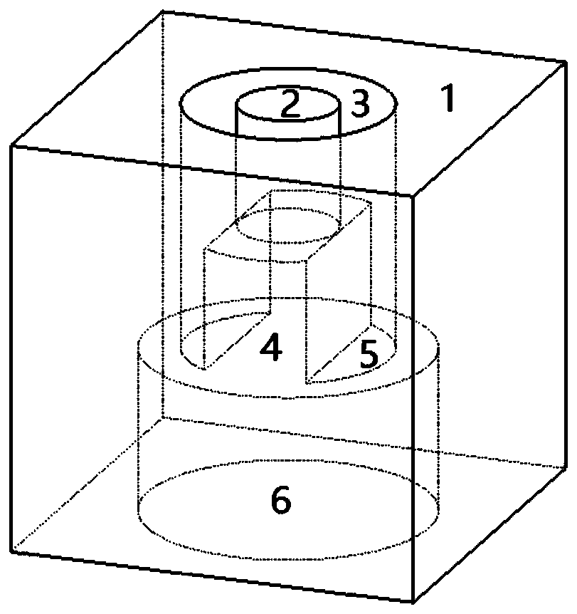
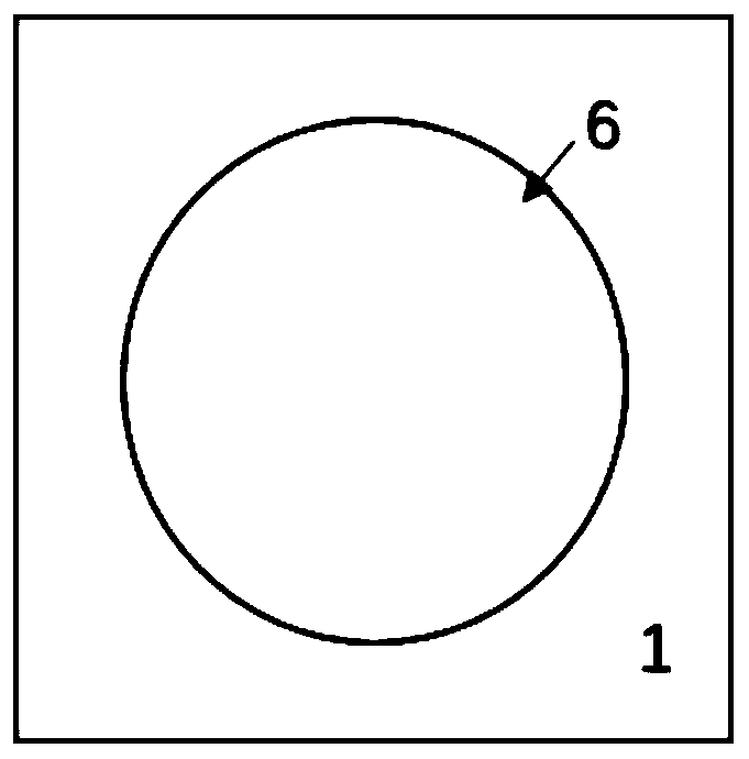
[0046] Such as Figure 2-Figure 8 As shown, it is a structural schematic diagram of a capillary orifice with a multi-layer composite structure in an embodiment of the present invention. The capillary orifice is composed of a drainage component 6, an independent suspended component 2 and a bridge component 4 for ...


PUM

PropertyMeasurementUnit
diameteraaaaaaaaaa

Abstract

The invention discloses a capillary spray hole with a multi-layer composite structure and a manufacturing method of the capillary spray hole. The capillary spray hole is of the multi-layer composite structure composed of a drainage component, an independent hanging component, and a beam bridge component used for supporting the independent hanging component, wherein the beam bridge component is positioned between the drainage component and the independent hanging component, so that a cantilever beam structure is formed. Different from the manufacturing of common specially-shaped fibers, the manufacturing of the micron-size artificial blood vessel belongs to the high-end manufacturing in hollow tubes, under the premise that the index performance parameter is not changed, along with the progressive decrease of the size, the processing means are ceaselessly reduced sharply, but the manufacturing difficulty increases in the form of the index, and therefore, the manufacturing of the artificial microvessel with the outer diameter being 100 [mu] m or below is the technical problem. According to the technical scheme provided by the invention, the micro injection molding technology and the in-situ lamination manufacturing technology are used for the manufacturing of the capillary spray hole of the artificial microvessel for the first time, the capillary spray hole structure with three layers of hanging hollowly formed cavities is originally created, and thus the uniform and seamless connection of the wall of the artificial microvessel is guaranteed.

Description

technical field [0001] The invention relates to a capillary orifice in the field of micromachining, in particular to a capillary orifice with a multilayer composite structure and a manufacturing method thereof, which can be used in the fields of biology, medicine, 3D printing, textile machinery and the like. Background technique [0002] With the development of microfabrication and nanoscience and technology, in aerospace, electronics, optical fiber and office automation equipment, image display, medical equipment, hydraulic components and other industrial fields, micron-sized hollow tube special-shaped cross-section fibers (except round For example, artificial microvessels are an example. Microvessels are the peripheral blood vessels of the human body, with extremely small dimensions and extremely high performance requirements for the tube wall. Artificial microvessels are implantable medical devices, so the requirements from materials to manufacturing are very high. In ter...

Claims


Application Information

Patent Timeline
Patent Type & Authority Patents(China)
IPC IPC(8): A61F2/06B29C64/10
Inventor 姚锦元
Owner SHANGHAI HUIPU ELECTROMECHANICAL SCI & TECH CO LTD
Why Eureka
Try Eureka