
System and method for recycling warm water discharge from costal power plants

A technology for warm drainage and power plants, applied in the environmental field, can solve the problems of wasting energy, shortening the treatment period, environmental pollution, etc., and achieve the effects of accurately controlling the temperature of the air supply, improving the degree of comprehensive utilization, and improving the efficiency of composting

Active Publication Date: 2018-01-23
GUODIAN LONGYUAN POWER TECH ENG
View PDF15 Cites 1 Cited by
  • Summary
  • Abstract
  • Description
  • Claims
  • Application Information

AI Technical Summary

Problems solved by technology

The high-temperature aerobic composting process can be divided into medium-temperature period (temperature rises and falls below 50°C), high-temperature period (temperature above 50°C) and cooling-down maturity period (temperature falls below 50°C and cools down). The type and degree of fermentation are also different. The high-temperature aerobic composting technology widely used at present all adopts the method of natural accumulation and heating. The processing cycle of food waste is long, generally reaching about 30 days. The development of compost that can further shorten the processing cycle and stabilize the processing quality Technology is the way of the future
[0004] To sum up, the warm drainage of existing power plants is directly discharged without low-temperature waste heat utilization, which not only wastes a lot of energy, but also causes environmental pollution; high-temperature aerobic composting is an efficient and comprehensive process for treating kitchen waste, but Because the current composting process does not introduce an external heat source, it needs to go through medium and high temperature periods at the same time, which has a significant impact on the composting cycle, resulting in a longer composting cycle and incomplete killing of pathogenic bacteria.

Method used


Image

  • System and method for recycling warm water discharge from costal power plants

Examples


Embodiment

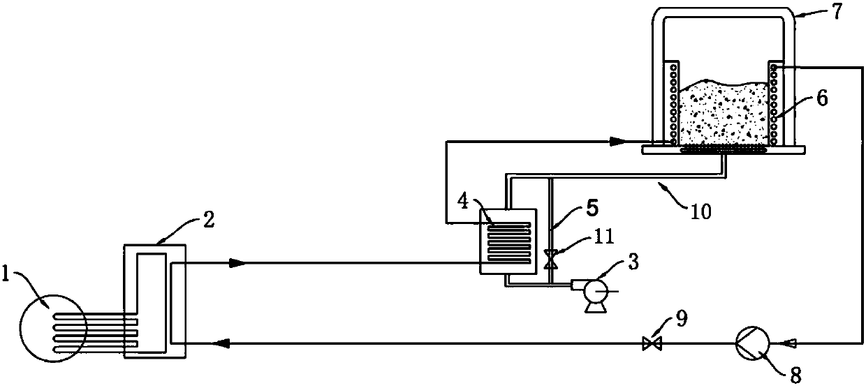
[0046] This preferred embodiment provides a system for recycling temperature and drainage of coastal power plants, the structure of which is as follows: figure 1 As shown, the system includes a heat pump 2, a hot water air heat exchanger 4, a heating buried pipe system 6 and an air supply subsystem: wherein,

[0047] The heat pump 2 is installed at the open cooling system of the condenser of the power plant; the heat medium water inlet of the evaporator is connected to the drain port of the temperature drain pipe 1 of the power plant, so that the evaporator absorbs the low-grade heat of the warm drain to gasify the circulating working medium , the cooled warm water is discharged from the heat medium water outlet of the evaporator; the refrigerant water inlet of the condenser is connected with the cold water outlet of the buried heating pipe system 6 to receive the medium water, so that the condenser can use the gasified circulating working fluid The heat released by liquefacti...


PUM


Abstract

The invention discloses a system for recycling warm water discharge from costal power plants; the system comprises: a heat pump that makes direct use of low-temperature waste heat of warm water discharge to heat medium water; a heating buried pipe subsystem arranged in a fermentation tank and which provides heat for the fermentation tank via the medium water heated by the heat pump; and an air supply subsystem that supplies air into the fermentation tank. The system has the advantages that low-temperature waste heat of warm water discharge can be utilized conveniently and efficiently by meansof the heat pump technology, comprehensive utilization rate of heat is increased, and the influence of the warm water discharge upon the environment is relieved; composting cycle can be shortened from30 days to 20 days and less, and composting efficiency is greatly improved. The system also comprises a hot water-air heat exchanger that preheats air and introduces it into the fermentation tank foroxygen supply, heat transfer efficiency can be improved, temperature rise time is shortened, the temperature of the fermentation tank is increased fast and is adjusted more reliably; in conjunction with buried pipe heating, the temperature can be maintained to about 60 DEG C, and the fermentation process is maintained on most efficiently.

Description

technical field [0001] The invention relates to a system and method for recycling temperature and drainage of coastal power plants, and belongs to the field of environmental technology. Background technique [0002] Power plant warm drainage is the cooling water drainage of the condenser open cooling system of the power plant. Coastal, river and river power plants are generally designed with an open circulating cooling water system based on practical considerations. The cooling water drawn from the water source is directly discharged through the warm drain pipe after absorbing the heat exhausted by the condenser. The open circulating cooling water system can better solve the power plant's demand for exhaust cooling, but the thermal pollution of the receiving water body is becoming more and more obvious under long-term operation, affecting the survival of fish and algae in the original ecological environment. With the increasing attention to environmental issues, properly so...

Claims


Application Information

Patent Timeline
IPC IPC(8): C05F17/00C05F17/02F24H4/02
CPCY02P20/129Y02P20/10Y02W30/40
Inventor 吕洲高维高霞马汉军
Owner GUODIAN LONGYUAN POWER TECH ENG
Learn More