Laser cladding device

A technology of laser and beam splitter, which is applied in the direction of tin feeding device, welding equipment, manufacturing tools, etc., can solve the problems of increasing wire feeding length, uneven blowing pressure of molten pool, and turbulent air flow, so as to ensure wire feeding speed and reduce melting The effect of covering space and compact structure

Pending Publication Date: 2018-01-26
SUZHOU UNIV
View PDF12 Cites 2 Cited by
  • Summary
  • Abstract
  • Description
  • Claims
  • Application Information

AI Technical Summary

Problems solved by technology

[0003] Chinese Patent Publication No. CN2608209Y discloses a wire feeder for laser cladding, which is characterized in that it includes a frame (1), a pinch wheel pair (2), a motor (3), and a reducer (4). The motor (3) and the reducer (4) are fixed on the frame (1), the output shaft of the motor (3) is connected with the input shaft of the reducer (4), and the driving wheel of the pinch wheel pair (2) is fixed On the output shaft of the reducer (4), the driven wheel is installed on the side of the driving wheel, and the metal wire for laser cladding is fed under the pinch between the driving wheel and the driven wheel, and the slave of the pinch wheel pair (2) The driving wheel is installed on the tail of the frame (1) on the spring pressure regulating slide mechanism, which can adjust the distance between the driven wheel and the driving wheel, and can also ensure a certain pressure feeding force, and the wire feeder of the pinch wheel pair (2). A straightening mechanism is also provided at the front position with the same direction, and the straightening mechanism includes several straightening rollers (5) arranged in two rows in a staggered manner, wherein the wire feeding guide (6) is fixed on the frame (1 ), the frame (1) is also provided with an angle adjustment and hanging mechanism (8) for fixed installation on the focusing mirror of the laser cladding processing machine. In the prior art lateral wire feeding device, due to structural limitations, The protective gas can only be blown sideways, and its blowing pressure on the molten pool is uneven, the air flow is disordered, and the protection effect is poor
[0007] The above laser cladding devices have the following problems: the wire feeding structure cannot be effectively integrated into an adjustable integrated laser cladding device, which is not conducive to saving space, and will increase the length of wire feeding, causing the wire to slide too long during the transmission process Unsmooth, resulting in the inability to effectively carry out the cladding work, and unable to ensure high-precision cladding layer shape and dimensional accuracy

Method used


Image

  • Laser cladding device
  • Laser cladding device
  • Laser cladding device

Examples


Embodiment Construction

[0043] The specific implementation manners of the present invention will be further described in detail below in conjunction with the accompanying drawings and embodiments. The following examples are used to illustrate the present invention, but are not intended to limit the scope of the present invention.

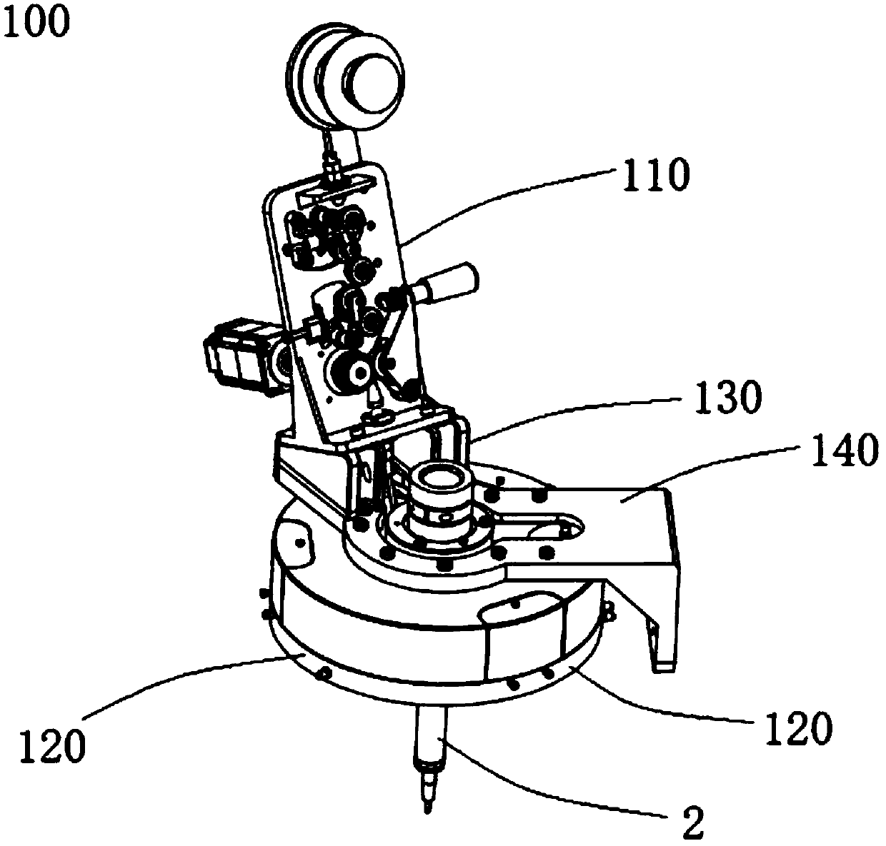
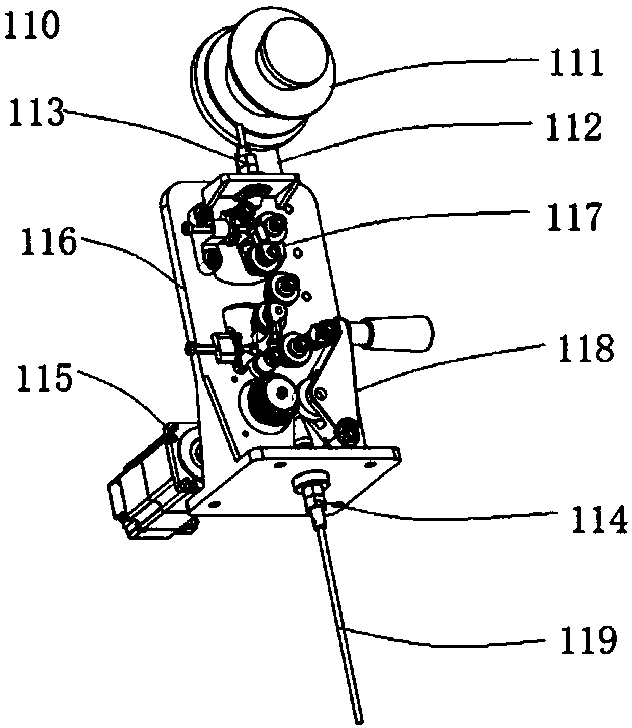
[0044] See figure 1 , Figure 4 , Figure 5 and Figure 6 , the laser cladding device of the present invention includes a wire feeder 110 and a nozzle 2, the wire feeder 110 and the nozzle are integrally arranged through a connecting bracket 140, the nozzle 2 is arranged under the connecting bracket, and the wire feeder 110 is arranged on Above the connection bracket 140, the connection bracket 140 connects the wire feeder 110 and the nozzle 2, the connection bracket 140 includes a body 143, a first extension 141 and a second extension 142, the first extension 141 is along the body 143 The second extension 142 extends along the vertical direction of the plane where the...


PUM


Abstract

The invention provides a laser cladding device. The laser cladding device comprises a wire feeder, a jetting head and a wire feeding pipe, wherein the wire feeder and the jetting head are connected through the wire feeding pipe, and the wire feeding pipe penetrates through the jetting head from one side of the jetting head in the direction of the wire feeder and is connected with the jetting head;the portions, penetrating through the jetting head in the direction of the wire feeder, of the wire feeding pipe are provided with an upper sealing gasket and a lower sealing gasket respectively, thelower sealing gasket is arranged on a supporting base, and the upper sealing gasket is arranged on a supporting cover; the lower sealing gasket comprises a fixing portion and a wire guiding pipe through hole, a columnar through hole is taken as the fixing portion and connected with the supporting base through a bolt, the diameter of the bolt is smaller than the inner diameter of the columnar through hole, the bolt can slide in the direction of the columnar through hole, and then position adjustment of the lower sealing gasket is achieved; and the upper sealing gasket comprises a fixing portion and a wire guiding pipe through hole and is connected with a support cover through the fixing portion. Therefore, the defects that in the prior art, a wire feeding hose can be bent in the moving cladding process of a jet nozzle, wires are different in frictional resistance in the conveying process, the speed of the wires changes after the wires leave from the jet nozzle, then high cladding layershape and size precision can not be guaranteed, and wire blocking is prone to occurring if the bending radius of the hose is very small are overcome.

Description

technical field [0001] The invention relates to a laser cladding device, which belongs to the field of laser processing. Background technique [0002] Laser cladding is a laser surface modification technology, which is to add cladding materials (powder feeding, wire feeding, preset, etc.) The thin layer of metal quickly reaches a molten state. At this time, relying on the heat conduction of the workpiece itself, it is rapidly solidified and crystallized into a cladding layer, so as to obtain a modified layer or repair layer with metallurgical bonding with the base material, low dilution rate, and various characteristics. Compared with traditional surface treatment technologies such as surfacing, thermal spraying, and electroplating, it has many advantages, such as a wide range of applicable material systems, controllable cladding layer dilution rate, metallurgical combination of cladding layer and substrate, and small thermal deformation of the substrate. , The process is e...

Claims


Application Information

Patent Timeline
IPC IPC(8): B23K1/005B23K3/06
CPCY02P10/25
Inventor 傅戈雁刘凡吉绍山石拓石世宏鲁健
Owner SUZHOU UNIV
Why Eureka
Try Eureka