Eureka AIR delivers breakthrough ideas for toughest innovation challenges, trusted by R&D personnel around the world.

Bearing fault diagnosis method and wireless network node device based on undersampling signal

A fault diagnosis and undersampling technology, applied in network topology, wireless communication, mechanical bearing testing, etc., can solve the problems of large data volume and high cost, and achieve the effect of less data volume, low power consumption and high efficiency

Active Publication Date: 2018-09-25
ANHUI UNIVERSITY
View PDF7 Cites 0 Cited by
  • Summary
  • Abstract
  • Description
  • Claims
  • Application Information

AI Technical Summary

Problems solved by technology

In the traditional bearing signal acquisition system, the sampling frequency is set to more than twice the highest frequency of the bearing signal to achieve oversampling. Therefore, the long-term monitoring data of the bearing is often huge in data volume, and the cost of data storage, transmission and calculation and analysis is also very high. high

Method used


Image

  • Bearing fault diagnosis method and wireless network node device based on undersampling signal
  • Bearing fault diagnosis method and wireless network node device based on undersampling signal
  • Bearing fault diagnosis method and wireless network node device based on undersampling signal

Examples


Embodiment 1

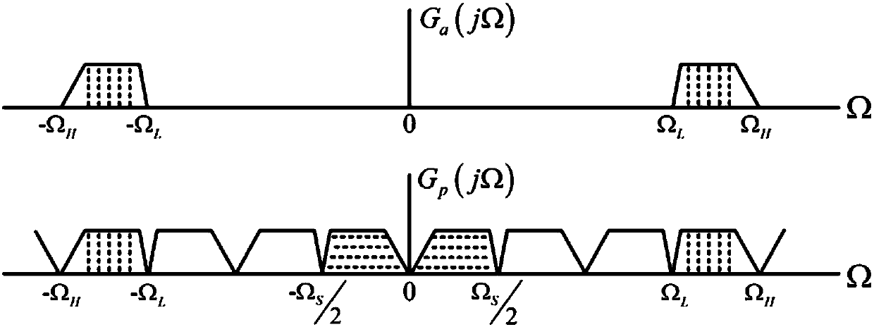
[0061] This embodiment is to clearly illustrate the frequency band replication process of the subsampling process. a continuous time signal g a The continuous-time Fourier transform G of (t) a (jΩ) such as image 3 As shown above, the signal is a typical bandpass signal. Set the sampling frequency Ω S =2·B=2Ω H / 4, get the sampling signal g p The continuous-time Fourier transform of (t) is:

[0062]

[0063] G p (jΩ) to get the spectrum as image 3 As shown below, it can be seen that the original bandpass bands with vertical dashed lines are replicated on the frequency axis, and one of them is replicated to the baseband with horizontal dashed lines. This process is signal aliasing. By making full use of the principle of signal aliasing, the high-frequency band-pass signal can be under-sampled with a sampling frequency lower than the Nyquist sampling rate, and then the original band-pass signal can be analyzed from the baseband signal. information.

Embodiment 2

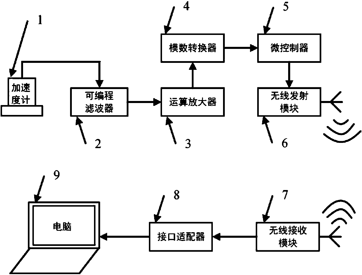
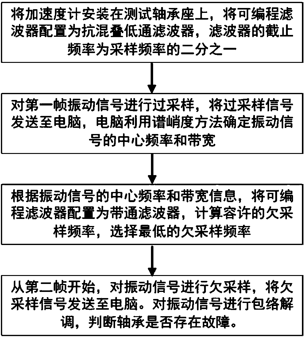
[0065] This embodiment illustrates the practicability and superiority of the present invention with a motor bearing with an outer ring fault. The model of the test bearing is NSK-6002Z, the speed of the motor is 3200rpm, and the characteristic frequency f of the outer ring fault of the bearing can be calculated BPFO 190Hz. use figure 1 As shown in the wireless network node device proposed by the present invention, according to step 1 of the method of the present invention, the wireless network node module in the device of the present invention is installed on the bearing seat to be tested. The sampling frequency is set to 25kHz, the sampling time is 1 second, the programmable filter 2 is set as a low-pass anti-aliasing filter, and the filter cutoff frequency is 12.5kHz.

[0066] According to step 2 of the method of the present invention, the bearing signal of the first frame is oversampled, and the oversampled bearing data is sent to the computer 9 through the wireless trans...


PUM


Abstract

The invention discloses a bearing fault diagnosis method based on undersampling signals and a wireless network node device, including: (1) an accelerometer is installed on a bearing seat to be tested, and a programmable filter is configured as an anti-aliasing low-pass filter ; (2) carry out oversampling to the vibration signal of the first frame, send the signal to the computer through the wireless module, and use the spectral kurtosis method to determine the center frequency and bandwidth of the vibration signal; (3) according to the center frequency and bandwidth, the programmable filter The filter is configured as a band-pass filter, calculates the allowable undersampling frequency, and selects the lowest undersampling frequency; (4) From the second frame, the vibration signal is undersampled, the undersampling signal is sent to the computer, and the vibration signal is packaged. Network demodulation to analyze bearing faults. The invention has the advantages of significantly reducing the sampling frequency and data length of the vibration signal, further reducing the memory occupation, power consumption and data transmission time of wireless network nodes, and improving the efficiency of bearing fault diagnosis.

Description

technical field [0001] The invention relates to the technical field of bearing fault diagnosis, in particular to a bearing fault diagnosis method based on undersampling signals and a wireless network node device. Background technique [0002] With the continuous development of wireless Internet of Things technology, more and more key devices use wireless technology to transmit the data collected by sensors to the information processing center. Since the wireless sensor technology does not need to lay cables, it simplifies the installation and replacement of sensors, and it is also convenient to arrange more sensors to obtain various status information of machinery and equipment. [0003] Using modern data mining and analysis methods such as machine learning, artificial intelligence, and big data, the massive data collected by multiple sensors can improve the accuracy of equipment status monitoring and fault diagnosis. On the other hand, massive data occupies more storage sp...

Claims


Application Information

Patent Timeline
Patent Type & Authority Patents(China)
IPC IPC(8): G01M13/04H04L29/08H04W84/18
CPCY02D30/70
Inventor 陆思良钱刚潘从元刘永斌
Owner ANHUI UNIVERSITY
Why Eureka
Eureka Blog
Learn More