High Power Microwave Radial Line Mode Conversion Slot Antenna
A high-power microwave and mode conversion technology, applied in the field of radiation antennas, can solve the problems of high-power microwave antennas such as low compactness, limited power capacity, and difficulties in high-frequency application
- Summary
- Abstract
- Description
- Claims
- Application Information
AI Technical Summary
Problems solved by technology
Method used
Image
Examples
Embodiment 1
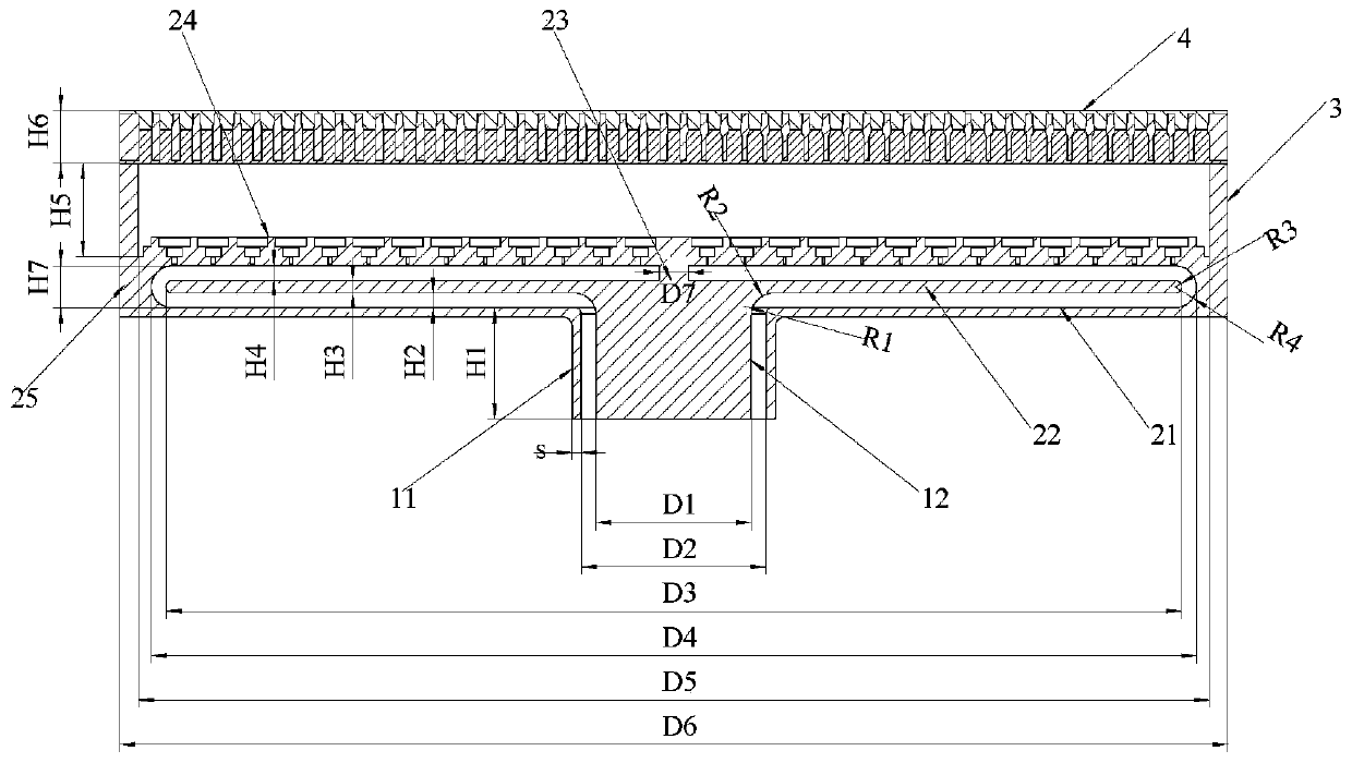
[0051] Provide N=10 below, be used for 12GHz (being that the frequency of input microwave source is 12GHz, corresponding microwave wavelength is 25mm) the concrete design dimension of an embodiment of the high-power microwave continuous transverse stub slot radial line antenna:
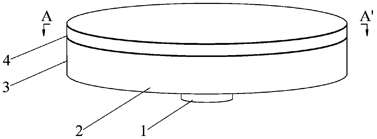
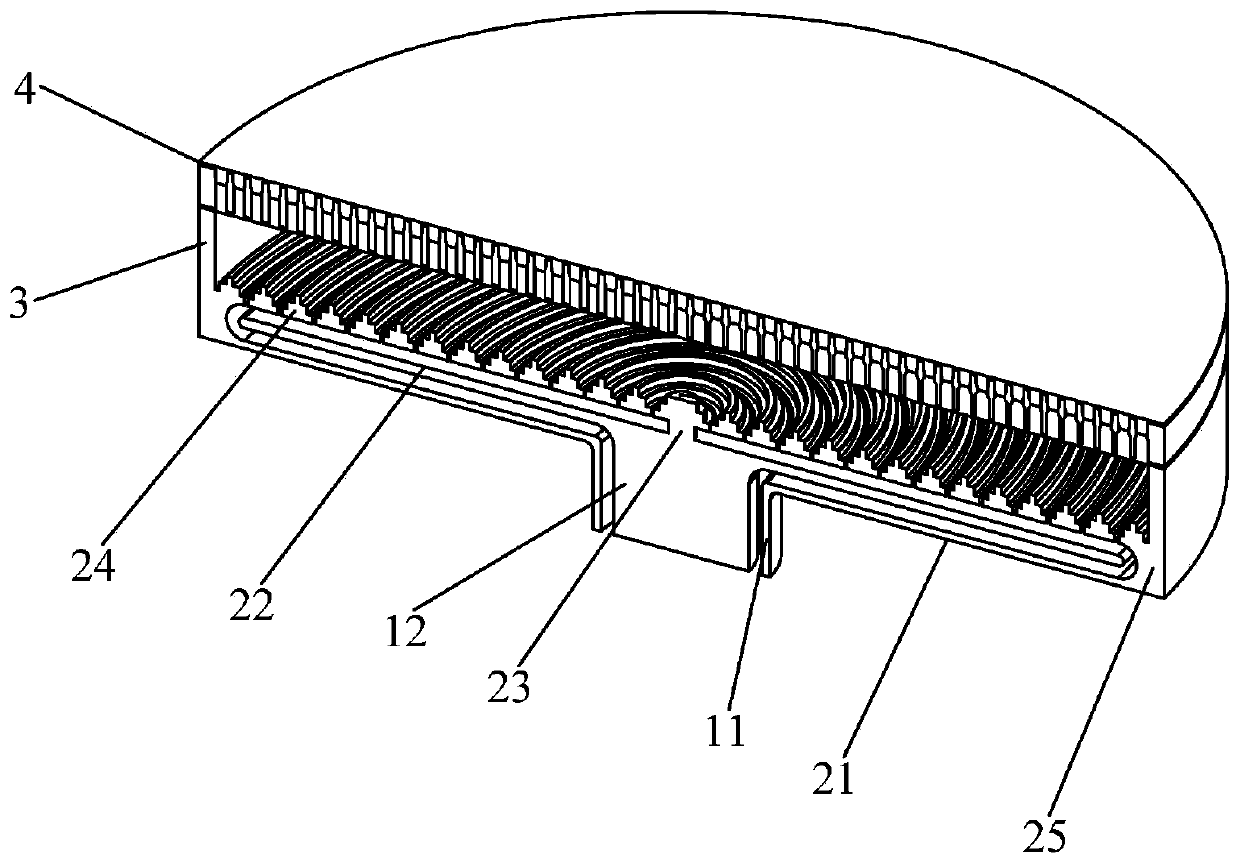
[0052] At this frequency, the diameter D1 of the inner conductor 11 of the coaxial waveguide 1 and the inner diameter D2 of the outer conductor 12 should satisfy According to actual needs, select D1=100mm, D2=119mm, the length of outer conductor 12 H1=60mm, and the length of inner conductor H1+H2=60+9.5=69.5mm; choose radial line leaky waveguide 2 waveguide wall 25 according to actual needs The outer diameter D6=560mm, under the premise that the microwave is transmitted without loss in the radial line leaky waveguide 2, the simulation optimization obtains the chamfer radius R1=3.9mm at the connection between the outer conductor 11 and the radial line bottom plate 21, The radius of the chamfer at the ...
Embodiment 2
[0058] Provide N=13 below, be used for 14.2GHz (being that the frequency of input microwave source is 14.2GHz, corresponding microwave wavelength is 21.03mm) the specific design dimension of an embodiment of the high-power microwave continuous lateral stub slot radial line antenna:
[0059] At this frequency, the diameter D1 of the inner conductor 11 of the coaxial waveguide 1=84mm, the inner diameter D2=100mm of the outer conductor 12, the length H1=60mm of the outer conductor 12, and the length of the inner conductor is H1+H2=60+8= 68 mm; the outer diameter D6 of the waveguide wall 25 of the radial line leaky waveguide 2 = 600 mm, the chamfer radius R1 of the connection between the outer conductor 11 and the radial line bottom plate 21 = 3.28 mm, the inner conductor 12 is connected with the radial line middle plate 22 Chamfer radius R2 = 12.01mm; inner diameter D4 of waveguide wall 25 of radial line leaky waveguide 2 = 572.5mm, radius of fillet inside waveguide wall R4 = 11.3...
Embodiment 3
[0065] Provide N=17 below, be used for 18GHz (being that the frequency of input microwave source is 18GHz, corresponding microwave wavelength is 16.7mm) the specific design dimension of an embodiment of the high-power microwave continuous lateral stub slot radial line antenna:
[0066] At this frequency, the diameter D1 of the inner conductor 11 of the coaxial waveguide 1 = 66.7mm, the inner diameter D2 of the outer conductor 12 = 79.3mm, the length H1 of the outer conductor 12 = 60mm, and the length of the inner conductor is H1+H2=60+ 6.3 = 66.3mm; the outer diameter D6 of the waveguide wall 25 of the radial line leaky waveguide 2 = 600mm, the chamfer radius R1 of the connection between the outer conductor 11 and the radial line bottom plate 21 = 2.6mm, the inner conductor 12 and the radial line center The chamfer radius R2 at the joint of the plates 22 is 9.5 mm; the inner diameter of the waveguide wall 25 of the radial line leaky waveguide 2 is D4 = 589.5 mm, and the radius ...
PUM
 Abstract
Description
Claims
Application Information
 - R&D
- Intellectual Property
- Life Sciences
- Materials
- Tech Scout
- Unparalleled Data Quality
- Higher Quality Content
- 60% Fewer Hallucinations
Browse by: Latest US Patents, China's latest patents, Technical Efficacy Thesaurus, Application Domain, Technology Topic, Popular Technical Reports.
© 2025 PatSnap. All rights reserved.Legal|Privacy policy|Modern Slavery Act Transparency Statement|Sitemap|About US| Contact US: help@patsnap.com


