
Direct current electric energy conversion method and system with DCDC module automatic conversion function

A DC power and automatic switching technology, which is applied in the direction of converting DC power input to DC power output, power network operating system integration, and adjusting electrical variables. It can solve the problem of large inductor volume, large inductor saturation current, and small inductor peak current. minor issues

Active Publication Date: 2018-02-02
SHENZHEN HOTCHIP TECH
View PDF6 Cites 10 Cited by
  • Summary
  • Abstract
  • Description
  • Claims
  • Application Information

AI Technical Summary

Problems solved by technology

In the prior art, there is only one DCDC module in a power conversion system. When the output current is large, the saturation current of the inductor is large, and the volume of the inductor is also large; it is obviously not suitable for portable applications due to space constraints. , it is necessary to use a small inductance, the peak current of a small inductance is small, and the heat is more serious when the load is heavy, so the output power ratio of a single DCDC module is limited

Method used


Image

  • Direct current electric energy conversion method and system with DCDC module automatic conversion function
  • Direct current electric energy conversion method and system with DCDC module automatic conversion function
  • Direct current electric energy conversion method and system with DCDC module automatic conversion function

Examples


Embodiment Construction

[0051] Embodiments of the present invention will be described in further detail below in conjunction with the accompanying drawings.

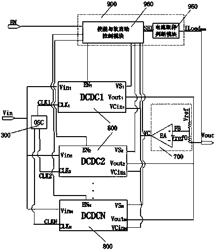
[0052] like figure 1 A direct current power conversion method for automatic switching of DCDC modules is shown, comprising the following steps:

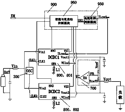
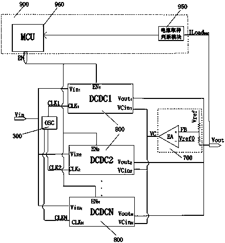
[0053] A: Set N in parallel for the input DC voltage V in converted to the output voltage V out The DCDC module 800, N is the number of the current power conversion module 800, and the value of N is a natural number ranging from 1 to M; it is set for the output voltage V out The output voltage detection and feedback module 700 for detection and feedback is used to provide the working clock signal CLK for N DCDC modules 800 at the same time N The clock signal module 300; the value of M can be any value between 2 and 100, of course, the more commonly used values ​​of M are 2, 3, 4, 6, 8 and 10;

[0054] B: The output voltage detection feedback module 700 samples the output voltage and compares it wi...


PUM


Abstract

Disclosed is a direct current electric energy conversion method and system with a DCDC module automatic conversion function. The system comprises N DCDC modules arranged in parallel, an output voltagedetection and feedback module and a clock signal module for providing working clock signals; a control module detects a current which is output to an external load, and works out that the number of the DCDC modules which need to be started is Q according to the value of the load current, and outputs enabling and starting control signals to Q DCDC modules; the working clock signals CLKN of the Q DCDC modules are the same in period, and the phase difference of each working clock signal CLKN is equal to 360 degrees / Q; the multiple paths of DCDC modules are connected in parallel, so that a relatively high current can be output and the system power consumption is also lowered; the multiple paths of DCDC modules are arranged on the same chip, so that quite high parameter consistency characteristic and high current balance characteristic in each path are achieved; and by virtue of time-sharing soft start and phase shifting time-sharing control, overcharging can be avoided, the ripple wave ofthe power supply output voltage is lowered, and more stable output characteristic is realized.

Description

technical field [0001] The invention belongs to a direct current power conversion circuit and system; in particular, it relates to a current mode direct current power conversion method and system with a plurality of direct current power conversion units. Background technique [0002] Switching regulators commonly used in DC power conversion in the prior art include BUCK mode switching regulators, BOOST mode switching regulators and BUCK-BOOST mode switching regulators. Regardless of the mode of switching regulators, there is usually only one DCDC conversion circuit. When When the output current is large, the efficiency is low, the heat generation is large, and the output ripple is also large, which requires a large saturation current of the inductor. In the prior art, there is only one DCDC module in a power conversion system. When a large output current is required, the saturation current of the inductor is large, and the volume of the inductor is also large; it is obviousl...

Claims


Application Information

Patent Timeline
IPC IPC(8): H02M3/158H02M1/36H02J9/06
CPCH02J9/061H02M1/36H02M3/1582Y04S20/20Y02B70/30
Inventor 张海波麦凯李盛峰柏志彬
Owner SHENZHEN HOTCHIP TECH
Learn More