
Dispersive atomic fluorescence multi-channel simultaneous detection method based on digital micromirror device (DMD)

An atomic fluorescence and detection method technology, applied in the field of atomic fluorescence spectroscopy, can solve the problems of inaccurate analysis of fluorescence wavelength information, the need to improve the detection accuracy results, waste of target element solutions, etc., to avoid inter-channel interference, avoid errors, and detect high precision effect

Active Publication Date: 2018-02-06
JILIN UNIV
View PDF3 Cites 11 Cited by
  • Summary
  • Abstract
  • Description
  • Claims
  • Application Information

AI Technical Summary

Problems solved by technology

The disadvantages of this method are: the detection efficiency is low, the detection time is long, the target element solution is wasted, and the fluorescence wavelength information of each element cannot be accurately analyzed. Flame intensity is not the same, as well as the influence of scattering interference caused by carrier gas and water vapor, resulting in some slight deviations in the results of different detections at the same time, and the detection accuracy needs to be improved

Method used


Image

  • Dispersive atomic fluorescence multi-channel simultaneous detection method based on digital micromirror device (DMD)
  • Dispersive atomic fluorescence multi-channel simultaneous detection method based on digital micromirror device (DMD)
  • Dispersive atomic fluorescence multi-channel simultaneous detection method based on digital micromirror device (DMD)

Examples


Embodiment Construction

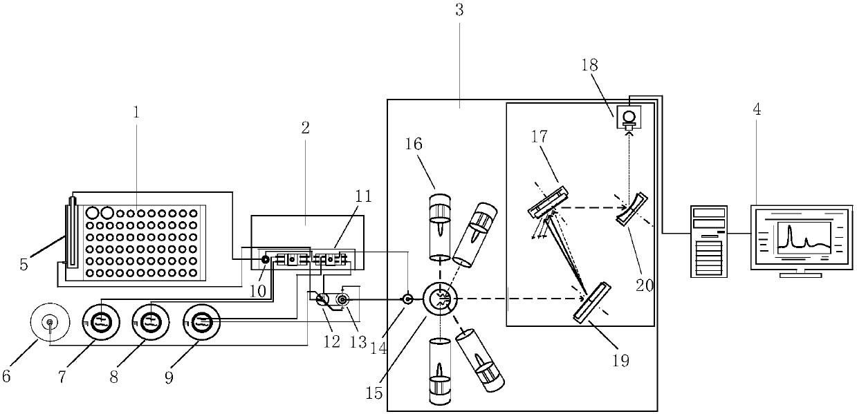
[0028] Such as figure 1 As shown, the DMD-based dispersive atomic fluorescence spectrometer includes an autosampler 1 , an intermittent flow system 2 , a fluorescence host 3 and a data processing system 4 .

[0029] Wherein the autosampler 1 and the intermittent flow system 2 include a sampling arm 5, an Ar gas cylinder 6, dilute hydrochloric acid 7, sodium borohydride solution 8, a waste liquid container 9, a syringe pump 10, a peristaltic pump 11, a reactor 12 and a Stage gas-liquid separator 13. The fluorescence host 3 includes a secondary gas-liquid separator 14, an atomizer 15, an excitation light source 16 and a dispersive atomic fluorescence detection system, and the dispersive atomic fluorescence detection system includes a DMD 17, a photomultiplier tube (PMT) 18, a grating 19 and a concave mirror 20. The excitation light source excites the atoms of the element to be measured in the argon-hydrogen flame of the atomizer, and the generated atomic fluorescence signal en...


PUM


Abstract

The invention relates to a dispersive atomic fluorescence multi-channel simultaneous detection method based on a digital micromirror device (DMD). The method is based on a DMD-based dispersive atomicfluorescence detection system and is used for simultaneously detecting multi-channel atomic fluorescence, thus avoiding the influence of the different time detection of the atomic fluorescence on light intensity, reducing noise effect and improving stability; furthermore, the method can save target element solutions, and the target element solutions can be concentrated together so as to be detected. In a sample detection process, an excitation light source combination mode is determined according to the concentration of each element to be detected, and the elements to be detected are excited at the same time, so that the error caused by the difference of the concentrations of the different elements can be effectively avoided. According to the compensation coefficient of spectral peak fluorescence intensity, the spectral peak fluorescence intensities of the elements which are to be detected and have overlapping spectral peaks can be compensated, so that the problem of spectral peak absorption caused by spectral peak overlapping can be solved, and inter-channel interference is effectively avoided; therefore, the method can be used for accurately determining the actual contents of theelements to be detected and is high in detection accuracy.

Description

Technical field: [0001] The invention belongs to the technical field of atomic fluorescence spectroscopy, in particular to a DMD-based multi-channel simultaneous detection method of dispersed atomic fluorescence. Background technique: [0002] Atomic fluorescence spectrometry is a detection method that collects, processes, analyzes and finally obtains qualitative and quantitative information on the fluorescence spectrum generated by the ground state atoms of the target element excited by specific frequency radiation light. Atomic fluorescence spectrometers are designed and produced based on this method. In the existing atomic fluorescence technology, the method of hydride generation is used to make the target element react to generate the corresponding hydride, which is separated from the high-temperature element that is difficult to atomize and easily produces metal oxide to eliminate the interference on the test of the target element. However, the elements that can be sepa...

Claims


Application Information

Patent Timeline
IPC IPC(8): G01N21/64
CPCG01N21/6404
Inventor 田地陶琛赵成威李春生周志恒
Owner JILIN UNIV
Learn More