
A fixed bed slag gasifier

A slag gasification and fixed bed technology, which is applied in the combination of fixed bed gasification, production of combustible gas, and fuel pre-dry distillation, etc., can solve the problems of increasing the amount of cooling and scrubbing gas, increasing the difficulty of extraction, and increasing the amount of phenol-containing wastewater treatment. , to achieve the effect of reducing the processing capacity, maximizing economic benefits, and reducing the amount of oil residue

Active Publication Date: 2019-09-06
CCTEG CHINA COAL RES INST
View PDF4 Cites 0 Cited by
  • Summary
  • Abstract
  • Description
  • Claims
  • Application Information

AI Technical Summary

Problems solved by technology

Although the tar and phenol content in the product of the gasification section is relatively low, the tar content in the coal gas is also diluted when all of them are passed into the dry distillation section, which increases the difficulty of extraction. volume also increased accordingly

Method used


Image

  • A fixed bed slag gasifier
  • A fixed bed slag gasifier

Examples


Embodiment 1

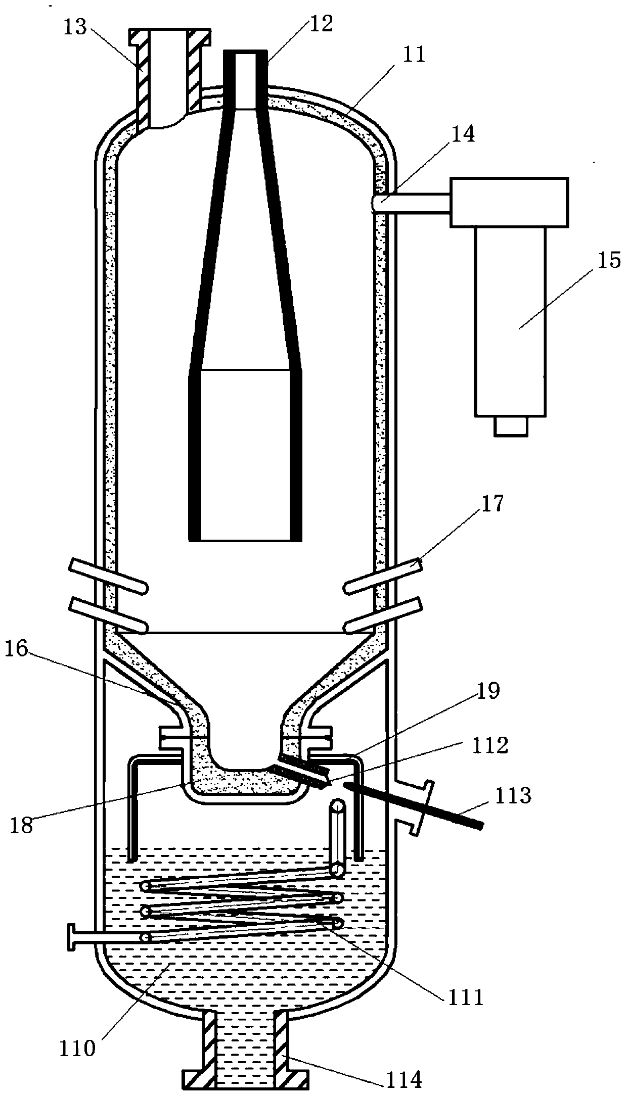
[0020] like figure 1 As shown, the present embodiment includes a furnace body 11, in which a different outlet pipe 12 arranged along the axial direction of the furnace body 11 is arranged, and the different outlet pipe 12 includes an upper small-diameter section, a middle expansion section and a lower large-diameter section , wherein the upper small-diameter section passes through the top of the furnace body 11 to form a high-temperature gas outlet. The inner surface of the outlet pipe 12 is provided with a refractory material, and an annular cavity is formed between the side wall of the outlet pipe 12 and the side wall of the furnace body 11, and a feeding inlet 13 communicating with the annular cavity is provided on the top of the furnace body 11 , the side wall of the furnace body 11 is provided with a low-temperature gas outlet 14 communicating with the annular cavity, and the low-temperature gas outlet 14 is connected with a spray scrubber 15 for removing tar and phenols ...

Embodiment 2

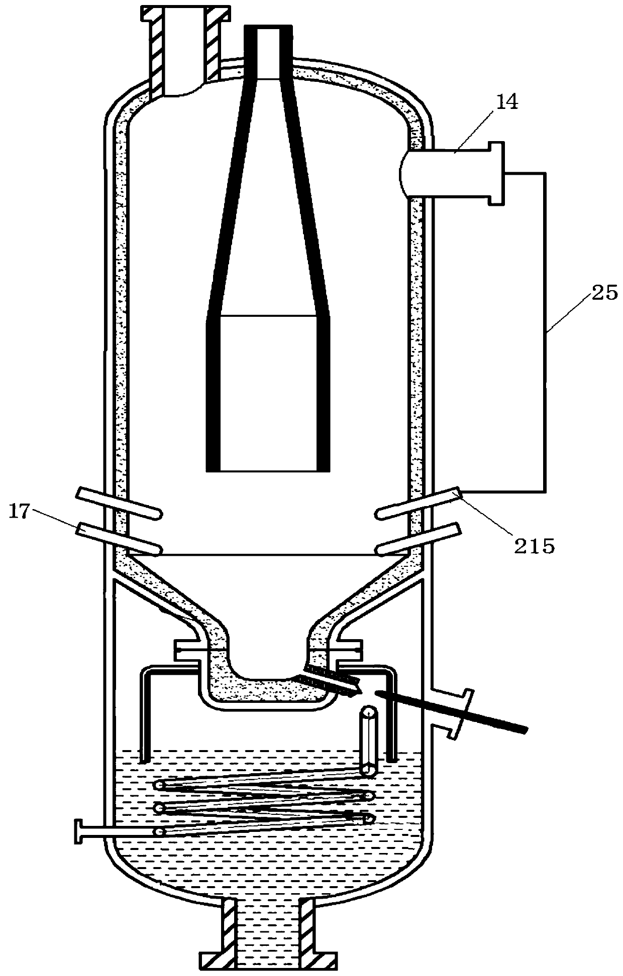
[0036] like figure 2 As shown, the difference between this embodiment and Embodiment 1 is that the low-temperature gas outlet 14 is connected to one end of the low-temperature gas circulation pipeline 25, and the other end of the low-temperature gas circulation pipeline 25 is connected to the low-temperature gas nozzle 215, and the low-temperature gas nozzle 215 is arranged above the gasification agent nozzle 17, and the nozzle of the low-temperature gas nozzle 17 faces the molten slag pool 16. Part of the high-temperature gas produced by the reaction exchanges heat with the gasification raw material in the inter-annulus gap, and after passing through the carbonization and drying sections, the low-temperature gas and tar and other products of the carbonization section after heat exchange pass through the low-temperature gas outlet 14, the low-temperature gas circulation pipeline 25 and the low-temperature The gas nozzle 215 leads into the high-temperature slag area, and the c...


PUM


Abstract

The invention relates to a fixed bed slag gasification furnace which comprises a furnace body. A special outlet pipe is arranged in the furnace body along the axial direction of the furnace body, thespecial outlet pipe comprises an upper small-diameter section, a middle extension section and a lower large-diameter section, the upper small-diameter section penetrates the top of the furnace body toform a high-temperature coal gas outlet, fire-resistant materials are arranged on the inner surface of the special outlet pipe, an annular cavity is formed between the side wall of the special outletpipe and the side wall of the furnace body, a feeding port communicated with the annular cavity is formed in the top of the furnace body, a low-temperature coal gas outlet communicated with the annular cavity is formed in the side wall of the furnace body, a funnel-shaped slag tank with uniform wall thickness is arranged at the bottom of the furnace body, a slag storage tank is firmly connected at the bottom of the slag tank, a plurality of gasifying agent sprayers are circumferentially and uniformly arranged on the side wall of the lower portion of the furnace body, and an included angle between each gasifying agent sprayer and a horizontal plane ranges from 0 degree to 90 degrees.

Description

technical field [0001] The invention relates to a fixed-bed molten slag gasifier, which belongs to the field of coal gasification devices. Background technique [0002] In the traditional fixed-bed slag gasifier, a coal inlet and a gas outlet are arranged on the top, and the lump coal is fed through the coal inlet, and the high-temperature gas produced by gasification is counter-currently exchanged for heat, and it is dried, dry-distilled, Gasification and final oxidative combustion. The resulting mixture of gasification gas, tar and water vapor is discharged from the gas outlet. Since there is only one gas outlet on the upper part of the gasifier, the gas velocity at the outlet is relatively high. [0003] In the actual production process, although the fixed bed slag gasifier uses lump coal as feed material, due to the entrainment of coal powder or the particle size of the lump coal is not up to the standard, the generated dust will be entrained with the air flow to form ...

Claims


Application Information

Patent Timeline
Patent Type & Authority Patents(China)
IPC IPC(8): C10J3/58C10J3/20C10J3/08C10J3/72C10J3/74C10J3/76C10J3/82C10J3/84
Inventor 陈亚飞董卫果晁俊楠郭辰辰李文博陈江徐春霞读刚
Owner CCTEG CHINA COAL RES INST
Learn More