High-intensity focused ultrasound device

一种聚焦超声波、高强度的技术,应用在超声波疗法、医药科学、加热外科器械等方向,能够解决高强度聚焦超声波生成装置使用寿命有限、不易实现快速愈合、手术费用升高等问题,达到增加维护费和使用时间、防止手术皮肤烧伤、防止皮肤烧伤的效果

Active Publication Date: 2018-02-13
金裕仁
View PDF5 Cites 5 Cited by
  • Summary
  • Abstract
  • Description
  • Claims
  • Application Information

AI Technical Summary

Problems solved by technology

[0004] However, due to the limited lifespan of high-intensity focused ultrasound generating devices, medical consumers who perform treatments for cosmetic purposes are exposed to higher surgical costs
[0005] In addition, although ultrasonic energy can be transmitted to a depth of 3-4.5mm below the skin surface (SMAS layer) to tighten the skin, it is difficult to achieve rapid healing due to the inability to regenerate a large amount of collagen at the same time
[0006] In addition, the service life is limited by the output of ultrasonic waves, etc., so when using an ultrasonic surgical device, it is necessary to periodically replace the separate cassette
[0007] At this time, due to the output of high-intensity focused ultrasonic waves, high heat will be generated on the transducer and cassette PCB of the separate cassette and the main PCB of the probe body, etc., which will make the service life of the product longer than originally planned. The limit value is shorter, and frequent replacement of the handpiece will bring a large burden on the cost of consumables to the user, so it is urgent to introduce a cooling unit that can effectively cool the heat generated in the main body to extend the life of the cartridge
[0008] In addition, even if such a cooling unit is introduced, the exact surgical location cannot be confirmed in real time, which may lead to repeated operations, causing skin damage and burns

Method used


Image

  • High-intensity focused ultrasound device
  • High-intensity focused ultrasound device
  • High-intensity focused ultrasound device

Examples


Embodiment Construction

[0030] In order to fully understand the present invention, preferred embodiments of the present invention will be described with reference to the accompanying drawings. The embodiments of the present invention can be transformed into various forms, and the protection scope of the present invention should not be limited to the embodiments described in detail below. This embodiment is provided to more completely describe the present invention to those skilled in the art. Therefore, shapes and the like of elements in the drawings may be presented exaggeratedly to enhance clarity of description. It should be noted that the same reference numerals are assigned to the same members in the respective drawings. Also, a detailed description of well-known functions and configurations that may unnecessarily obscure the gist of the present invention will be omitted.

[0031] Such as figure 1 with figure 2 As shown, the present invention includes: a handpiece main body 100 (handpiece),...


PUM


Abstract

The present invention relates to a high-intensity focused ultrasound device, and more specifically, to a high-intensity focused ultrasound device which has a structure changed so as to enable a disposable separable cartridge to be attached and detached, and which enables a doctor, who is the person performing a procedure, to obtain, through a scanning unit of a transducer for ultrasonic conversion, coordinates of a skin tissue of a subject undergoing the procedure, thereby allowing for an accurate procedure point to be checked in real time, thus allowing for a procedure to be performed on an accurate point on a skin tissue, without repeated procedures. The present invention relates to a high-intensity 
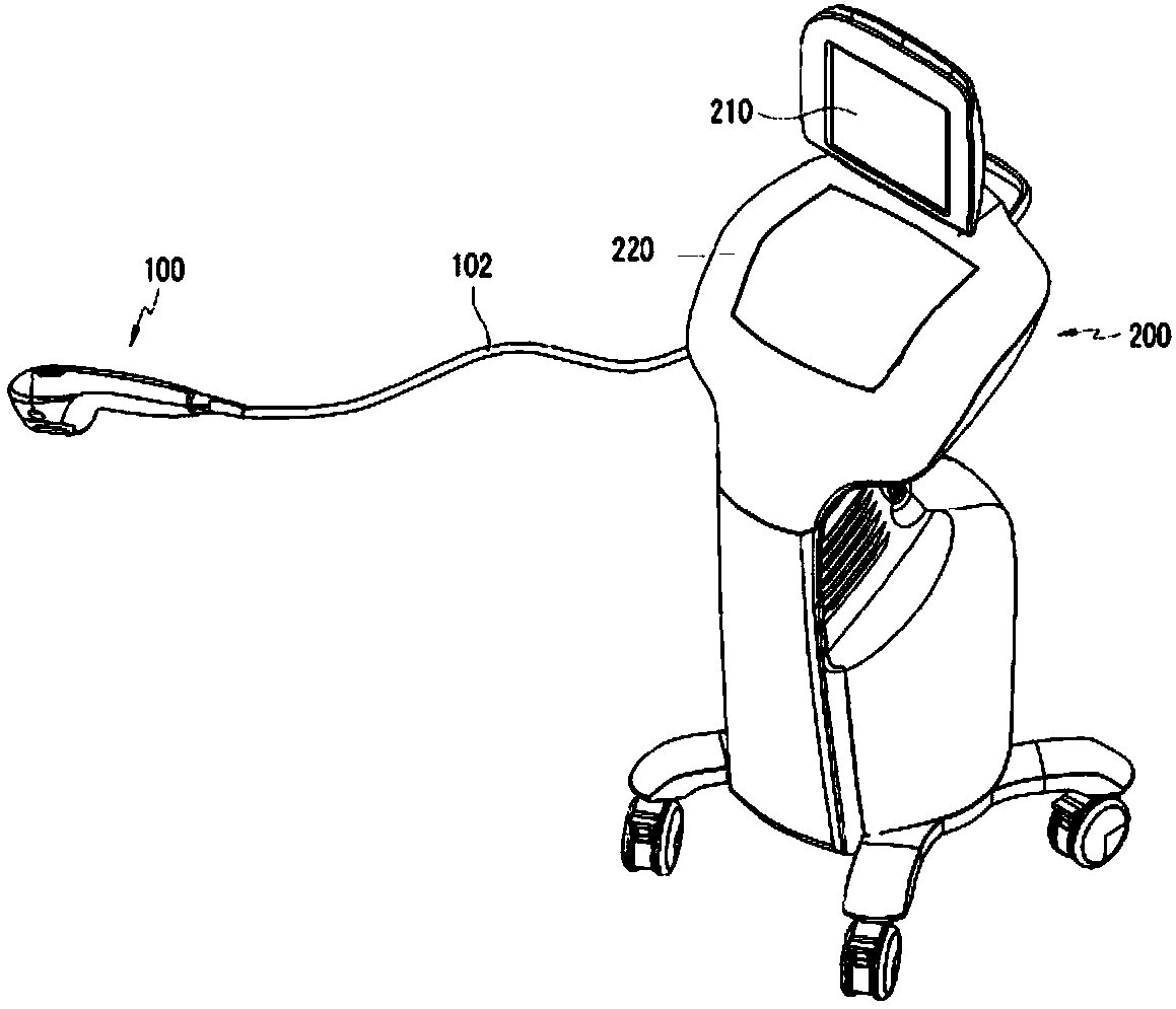
focused ultrasound device comprising a hand piece comprising: a hand piece body electrically connected by a wire to a freely movable moving body; and a separable 
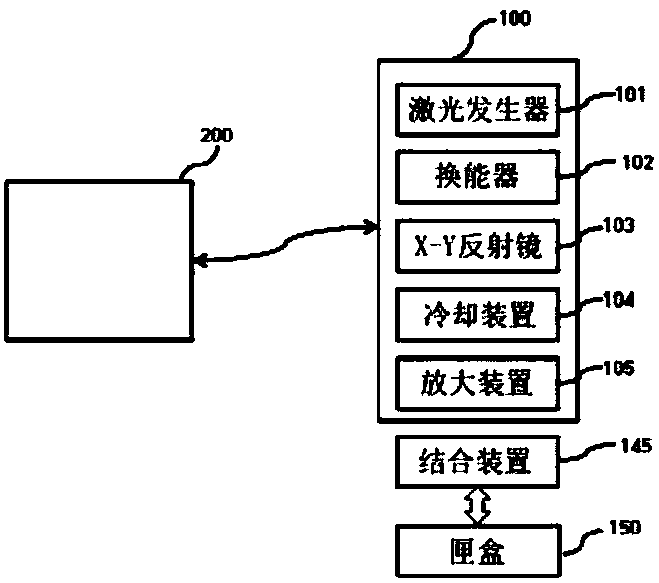
cartridge disposably coupled to the hand piece body. The hand piece body comprises: a laser generator which fractionally transfers energy so as to facilitate the synthesizing of collagen; a transducer for ultrasonic conversion which receives electrical energy that has been impedance-matched by going through the processes of frequency generation and power amplification, converts the electrical energy into high-intensity focused ultrasound and irradiates same, or which receives reflected ultrasound; and an X-Y reflection mirror which undergoes in parallel a forward / backward movement and a tilting movement inside the hand piece body, and consecutively forms HIFU foci in a single row, or consecutively forms HIFU foci in aplurality of rows, or consecutively forms foci in a circular shape; a cooling device which supplies cooling gas to the separable cartridge; and a zoom-in device which zooms-in an image formed by thereflected ultrasound. The separable cartridge comprises: a cooling passage which enables cooling gas to be injected and to flow on the bottom surface of the separable cartridge, thereby lowering the temperature; and a transparent transmittance member which supports the cooling passage, and adheres to a skin tissue so as to enable the laser and the high-intensity focused ultrasound to pass throughand reach the skin. The 
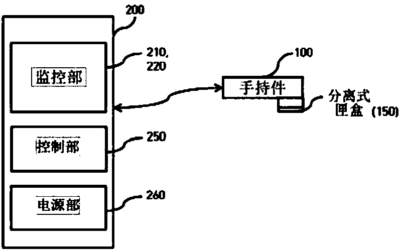
moving body comprises: a control unit comprising a transducer for ultrasonic conversion-module, a reflection mirror control module, a cooling module and a coordinate module, the transducer for ultrasonic conversion-module controlling the processes of frequency generation and power amplification of the transducer for ultrasonic conversion, and controlling power, frequency, duty cycle, focus size and pulse repetition frequency, the reflection mirror control module controlling the forward / backward movement and the tilting movement of the X-axis and the Y-axis of the reflection mirror, the cooling module lowering the temperature of the cooling device if re-treatment is performed, and the coordinate module receiving information on coordinates converted through the transducer for ultrasonic conversion, and figuring out a site that is currently being treated; a monitor unit comprising an indicator for indicating information related to a procedure of a person performingthe procedure, and a touch screen for the person performing the procedure to operate or control the high-intensity focused ultrasound generation device; and a power unit for supplying high-intensityfocused ultrasound power.

Description

technical field [0001] The present invention relates to a high-intensity focused ultrasound device. More specifically, it relates to a structure in which a disposable separable cassette can be detached and assembled, and the operator, that is, a doctor, can scan with a transducer through ultrasonic conversion. It is a high-intensity focused ultrasound device that can obtain the coordinates of the skin tissue of the surgical object by using a part to confirm the exact surgical location in real time, and perform surgery at the exact surgical location to avoid repeated operations. Background technique [0002] Generally speaking, High Intensity Focused Ultrasonic surgical unit (HIFU) is a technology that irradiates the ultrasonic waves generated in the transducer into the tissue, so as to use the heat energy generated by the focal point (focal point) for treatment. It is used in the treatment of liver cancer, breast cancer, uterine cancer, etc. Apply this principle to skin bea...

Claims


Application Information

Patent Timeline
Patent Type & Authority Applications(China)
IPC IPC(8): A61N5/06A61N7/02
CPCA61N5/06A61N7/02A61N7/00A61N2005/0644A61B18/14A61B2017/00477A61B2018/00005A61B2018/00017A61B2018/00994A61B2034/2063A61B2034/2065A61N5/0616A61N2005/005A61N2007/0034A61N2007/0052A61N2007/0069A61N2007/0091A61N5/067A61N2007/027
Inventor 金裕仁
Owner 金裕仁
Why Eureka
Try Eureka