Concrete pile suitable for foundation treatment

A technology for concrete pile and foundation treatment, applied in sheet pile wall, foundation structure engineering, construction, etc., can solve the problems of reducing the bearing capacity per unit area of ​​the foundation, unsuitable for foundation treatment engineering, and inability to transmit bearing capacity, etc. Bearing capacity and compressive modulus, improvement of foundation settlement or local settlement, simple construction method

Active Publication Date: 2018-02-16
宁波中淳高科股份有限公司
View PDF12 Cites 5 Cited by
  • Summary
  • Abstract
  • Description
  • Claims
  • Application Information

AI Technical Summary

Problems solved by technology

However, the construction process of this kind of sand-filled bamboo pile is complicated, and the quality controllability is poor. At the same time, in order to meet the requirements of sand filling and drainage during the construction process, the height of the bamboo joints on the pile body should be at least 100mm. The gap between the soil and the soil will increase the distance between the two piles, which will reduce the bearing capacity per unit area of ​​the foundation. It is not suitable for foundation treatment projects that require a higher bearing capacity per unit area; secondly, the filled sand and soil There is a weak link at the junction of the layers, where the friction force is small, and the bearing capacity of the pile body cannot be evenly and effectively transmitted to the soil around the pile through the bamboo joints, and cannot form a pile-soil community with it

Method used


Image

  • Concrete pile suitable for foundation treatment
  • Concrete pile suitable for foundation treatment
  • Concrete pile suitable for foundation treatment

Examples


Embodiment 1

[0028] Embodiment one, such as Figure 1 to Figure 2 as shown,

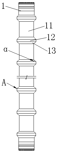
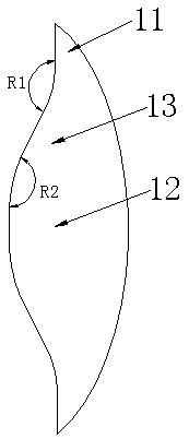
[0029] A concrete pile suitable for foundation treatment, comprising a pile body 1, the pile body 1 is integrally formed with a variable cross-section structure, diameter-expanding parts 12 are arranged at intervals on the pile body 1, and there are formed between adjacent diameter-expanding parts 12 The diameter-reducing part 11 is connected and reinforced by the constriction structure 13 between the reducing-diameter part 11 and the expanding-diameter part 12; Value ≤ 60mm.

[0030] In the embodiment, the enlarged diameter parts 12 are arranged at equal intervals.

[0031] The concrete pile of this embodiment is mainly suitable for soft soil foundation treatment projects when the thickness of the soft soil layer is not too large or the soft soil layer contains more thin silt interlayers. The construction method is to construct the concrete pile into the soft soil layer. During the construction process, the e...

Embodiment 2

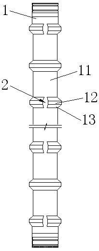
[0040] Embodiment two, such as image 3 as shown,

[0041] The concrete pile in this embodiment is similar in structure to the concrete pile in Embodiment 1, the difference is that in this embodiment, the diameter-expanding part 12 is a non-closed ring formed by opening a notch 2 .

[0042] In the embodiment, when the diameter-expanding part 12 is a non-closed ring, the positions of the notches 2 of two adjacent diameter-expanding parts 12 are staggered by 180° around the center of the diameter-expanding part 12 along the radial plane; The difficulty of demoulding can be reduced during the manufacture of concrete piles.

[0043] The concrete piles in this embodiment are mainly suitable for foundation treatment projects with deep soft clay and muddy soil in the foundation. The channel formed by the notch 2 and the outer wall of the reduced diameter part 11 gushes out to the ground, which solves the problem of excess static pore pressure of the soil generated during the constr...

Embodiment 3

[0044] Embodiment three, such as Figure 4 as shown,

[0045] The concrete pile in the present embodiment is similar to the concrete pile structure in the second embodiment, the difference is that in the present embodiment, one end of the concrete pile is provided with a pile-end diameter-expanding portion 14, and the axial length of the pile-end diameter-expanding portion 14 is 350mm to 650mm; when the middle and upper part of the foundation is hard crust or hard clay, the bottom is deep silt or soft plastic clay (or the bottom is hard crust or hard clay, and the top is deep mud or soft plastic clay ) situation, increasing the pile length cannot significantly improve the bearing capacity of the foundation soil. At this time, the concrete pile in this embodiment can be used. According to the actual engineering situation, the diameter expansion part 12 added at the pile end is placed in the hard shell layer or hard viscous In the soil layer, the diameter-expanding part 12 is c...


PUM


Abstract

The invention discloses a concrete pile suitable for foundation treatment. The concrete pile comprises a pile body which is a variable cross-section structure formed integrally, diameter expansion portions are arranged on the pile body at intervals, a diameter reduction portion is arranged between every two adjacent diameter expansion portions, and the diameter reduction portions and the diameterexpansion portions are connected and fastened through necking down structures; each diameter expansion portion is a closed ring or non-closed ring provided with a notch, and difference value between the radial width of the diameter reduction portions and that of the diameter expansion portions is smaller than or equal to 60 mm. The concrete pile has the advantages of being higher in practicabilityand applicability, the pile body directly make contact with an original soil body in the construction process, no weak link exists, and the foundation soil bearing capacity is promoted remarkably bymeans of expansion and vibration on the soil body by the diameter expansion portions; after the soil body is solidified, loads on the foundation soil are uniformly distributed into the foundation soilthrough the load bearing faces of the diameter expansion portions and the diameter reduction portions, a whole is formed by the foundation soil and soil around the pile, the foundation settlement problem is improved substantially, and the global stability of the foundation is improved; the concrete pile is low in manufacturing cost and good in economic benefits.

Description

technical field [0001] The invention relates to the technical field of foundation treatment engineering, in particular to the improvement of the vertical reinforcement structure in the foundation treatment engineering, and more precisely relates to a concrete pile suitable for foundation treatment. Background technique [0002] With the proposal of major strategic goals such as "building a powerful ocean country" and "green building and building industrialization", various construction projects have developed rapidly, but the land available for construction has been decreasing. Engineering has increased substantially. Weak soil has special physical and mechanical properties such as low strength, poor stability, and large deformation, which lead to its unique engineering problems, such as high water content in the soil, very poor water permeability, and pore water pressure will rise sharply after being subjected to strong loads , the compaction and consolidation performance ...

Claims


Application Information

Patent Timeline
Patent Type & Authority Applications(China)
IPC IPC(8): E02D5/48
CPCE02D5/48Y02E10/50
Inventor 许国林严天龙舒佳明袁海峰张日红
Owner 宁波中淳高科股份有限公司
Why Eureka
Try Eureka