Novel hydraulic clamp oil source

A technology of hydraulic fixture and hydraulic oil, applied in the field of hydraulic fixture oil source, can solve the problems of reducing the service life of hydraulic oil and energy, affecting test efficiency and result accuracy, waste and other problems, so as to achieve the effect of not producing energy waste.

Inactive Publication Date: 2018-02-16
力试(上海)科学仪器有限公司
View PDF0 Cites 0 Cited by
  • Summary
  • Abstract
  • Description
  • Claims
  • Application Information

AI Technical Summary

Problems solved by technology

[0003] (1) The working condition of the hydraulic fixture in the tensile testing machine is that it needs to be fast when clamping and loosening, so it needs a large flow instead of high pressure; when the fixture is in the clamped state for testing The cylinder of the hydraulic clamp hardly moves, and only requires a large clamping force and high pressure, so only a small flow is required; the oil source of the ordinary hydraulic clamp adopts a common motor to drive the hydraulic pump, which can only output a fixed pressure and flow , so it will cause a large amount of high-pressure oil to be diverted through the relief valve under the clamping high-pressure state, resulting in huge energy loss, and may even fail to reach the required high pressure and flow, which seriously affects the test efficiency and the accuracy of the results;
[0004] (2) An ordinary motor is used to drive the hydraulic pump, resulting in a large amount of high-pressure oil that needs to be diverted through the overflow valve, and the energy leakage causes serious heating problems. However, the conventional hydraulic station has overflow and heat during pressure maintenance, and usually requires air cooling or The way of water cooling not only increases the complexity of the system, but also reduces the service life of hydraulic oil and waste of energy;
[0005] (3) The hydraulic pump is driven by an ordinary motor, which will generate a lot of noise during work, which will bring trouble to the operator

Method used


Image

  • Novel hydraulic clamp oil source
  • Novel hydraulic clamp oil source
  • Novel hydraulic clamp oil source

Examples


Embodiment Construction

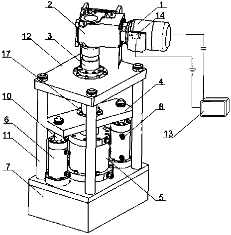
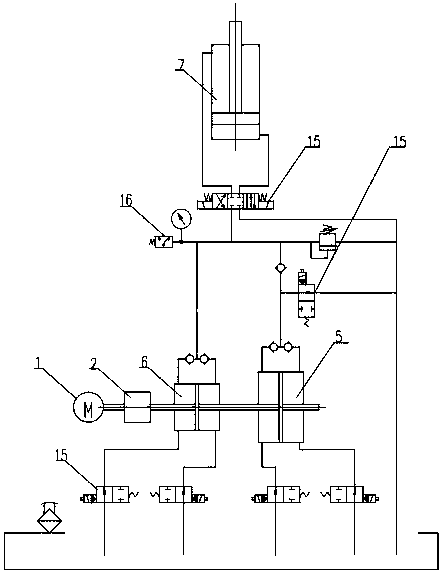
[0036] Such as figure 1 , 2 As shown, a new type of hydraulic clamp oil source described in the embodiment of the present invention includes a servo motor 1, a reducer 2, a screw 3, a connecting plate 4, a fast feed cylinder 5, a work feed cylinder 6, an oil tank 7, an induction Switch 8, support column 11, support plate 12, motion controller 13, photoelectric encoder 14, reversing valve 15, pressure sensor 16, screw nut 17;

[0037] The oil tank 7 is arranged at the bottom of the whole device, and hydraulic oil is stored in it to provide oil source for the hydraulic fixture; fast-forward oil cylinder 5 and work-feed oil cylinder 6 are installed above the oil tank 7; fast-forward oil cylinder 5 and work-feed oil cylinder 6 are located above it Supporting columns 11 are arranged externally;

[0038] A support plate 12 is fixed above the support column 11 for supporting the reducer 2, and a screw hole is arranged in the middle of the support plate 12;

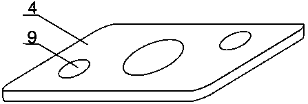
[0039] A connection pl...


PUM


Abstract

The invention discloses a new type of oil source for hydraulic clamps. The oil tank of the hydraulic clamp oil source is arranged at the bottom, and hydraulic oil is stored therein; a fast-feed oil cylinder and a work-feed oil cylinder are installed above the oil tank; and a fast-feed oil cylinder and a work-feed oil cylinder are installed above Connecting plate, a number of connecting holes are arranged on the connecting plate, the connecting holes are connected with the piston tops of the fast-forward oil cylinder and the work-feed oil cylinder; the servo motor is connected with the reducer; the output shaft of the reducer is connected with one end of the lead screw; the lead screw on the lead screw The female is connected to the connection board. Its beneficial effects are: the structure controls the confluence of hydraulic oil through the setting of the reversing valve, obtains the maximum required flow rate of the fast-forward oil cylinder and the required pressure of the work-in oil cylinder, and meets the clamping pressure requirements of the fixture; the servo motor piston lifts to provide pressure and supply Oil, no need for overflow and cooling, energy saving and environmental protection, improve the service life of hydraulic oil, the driving oil supply mode of screw and cylinder greatly reduces the impact of noise; the pressure sensor can feedback the pressure at all times, and control the output of different pressures through the motion controller.

Description

Technical field: [0001] The invention relates to a hydraulic clamp oil source, in particular to a hydraulic clamp oil source capable of closed-loop control of speed and pressure. Background technique: [0002] Tensile test refers to the test method for measuring the properties of materials under axial tensile load. When the test material is subjected to tensile test, it often needs to be clamped by clamps. Slipping, or the clamping force is too large to damage the sample, so the requirements for the fixture are more stringent. Among various fixtures, hydraulic fixture clamping can effectively solve the above problems. The hydraulic clamp can ensure the firm clamping of the test piece, however, there are still the following problems to be solved urgently in the clamping process of the hydraulic clamp: [0003] (1) The working condition of the hydraulic fixture in the tensile testing machine is that it needs to be fast when clamping and loosening, so it needs a large flow in...

Claims


Application Information

Patent Timeline
Patent Type & Authority Applications(China)
IPC IPC(8): F15B21/00F15B13/02F15B19/00F15B20/00
CPCF15B21/00F15B13/02F15B19/00F15B20/00
Inventor 王斌
Owner 力试(上海)科学仪器有限公司
Why Eureka
Try Eureka