A digital control method for single-phase pwm rectifier based on fpga

A digital control and rectifier technology, applied in the output power conversion device, the conversion of AC power input to DC power output, electrical components, etc., can solve the problems of long control delay, general, poor control effect, etc. The effect of loop gain, good application prospect and excellent control effect

Active Publication Date: 2020-05-29
西安翌飞核能装备股份有限公司
View PDF5 Cites 0 Cited by
  • Summary
  • Abstract
  • Description
  • Claims
  • Application Information

AI Technical Summary

Problems solved by technology

But it also has its disadvantages: analog control debugging is inconvenient, with the extension of equipment time, some parameters of the analog device will shift due to factors such as temperature drift and the control effect will deteriorate, and intelligent control algorithms cannot be added when the power is high and the switching frequency is low. Average control effect
At present, many devices are also using digital control algorithms. Digital control has unique advantages. All device parameters are consistent and easy to debug. There will never be temperature drift and aging effects. Adding intelligent control algorithms to low switching frequency and high power working conditions can achieve very Good control effect, but currently most of them use DSP to realize digital control, but DSP is limited by its running speed and shortcomings of sequential execution, and has a long control delay (conventional one-beat, half-beat, 1 / 4 The delay of shooting, different technical capabilities of different manufacturers), and at the same time, the DSP uses the timer to generate the carrier to realize the modulation of the modulation wave, and always modulates according to the regular sampling method, and the modulation error always exists; considering the above two factors, under the same switching frequency , can never achieve the good effect of analog control, let alone surpass the analog control

Method used


Image

  • A digital control method for single-phase pwm rectifier based on fpga
  • A digital control method for single-phase pwm rectifier based on fpga
  • A digital control method for single-phase pwm rectifier based on fpga

Examples


Embodiment Construction

[0024] Below in conjunction with specific embodiment and accompanying drawing, the present invention is described in further detail:

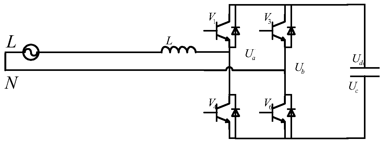
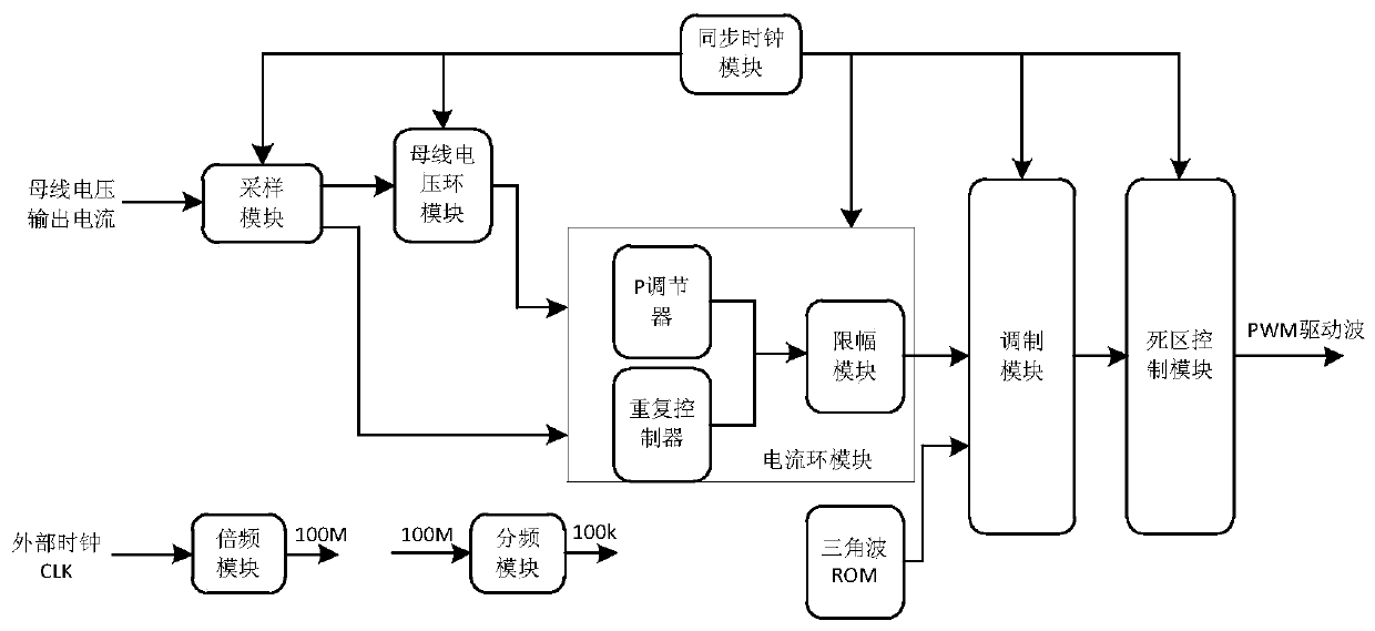
[0025] Such as figure 1 Shown is a single-phase PWM rectifier topology, control system composition diagram. The AC side of the single-phase H-bridge voltage inverter is connected to the power grid through a single-phase reactance, and the DC side of the inverter is connected to the capacitor to provide inverter voltage support through control. Its control system is as follows: DSP+FPGA processor combination scheme is adopted, and DSP realizes sequential logic control, fault logic control, and communication control with man-machine interface of PWM rectifier. FPGA realizes all digital control loops, including sampling module, bus voltage control module, current loop control module, repetition control module, modulation module and dead zone module.

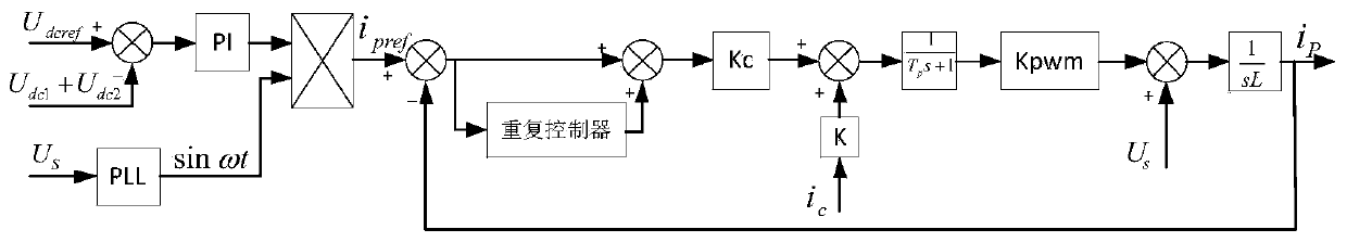
[0026] Such as figure 2 Shown is the control block diagram of the PWM rectifier. The details...


PUM


Abstract

A digital control method based on FPGA to realize a single-phase PWM rectifier, a. The frequency multiplication module realizes the frequency multiplication of the crystal oscillator frequency, and outputs 100MHz main frequency requirement; the frequency division module realizes the 100MHz main frequency frequency division output 100KHz; The pulse clock; b. The sampling module samples the bus voltage and output current and converts them into actual values; c. The bus voltage loop module uses the bus voltage in step b to obtain the active voltage regulation command; d. The output current of step b and step c The active voltage regulation command is sent to the current loop control, and the output current closed-loop control is carried out to obtain the modulated wave; e. The modulated wave and the triangular wave in step d realize SPWM modulation in the modulation module, and output two PWM waves; f. The dead zone module uses the steps The two channels of PWM input by e generate two complementary PWMs respectively. The PWM drives the IGBTi inverter bridge to act through hardware level conversion; the control delay is within 3us, and the best effect of DSP is 1 / 4 beat control delay; Increase the open-loop gain of each frequency point, and the control effect is better than that of analog control.

Description

technical field [0001] The invention belongs to the technical field of power electronics, and in particular relates to a digital control method for realizing a single-phase PWM rectifier based on FPGA, and realizes the digital control realization of double-loop + repeating controller based on FPGA. Background technique [0002] With the continuous development of the economy, the loads in the power grid are becoming more and more complex, and many high-end equipment are continuously connected to the power grid, such as the semiconductor industry, high-precision machining industry, servers, etc., and the requirements for the quality of the power grid are getting higher and higher. , Customers are beginning to pay attention to the harmonics and reactive power pollution of the power grid caused by the input of power electronic products such as power supplies and household appliances. The disadvantages of the conventional low-cost uncontrolled diode rectification topology are beco...

Claims


Application Information

Patent Timeline
Patent Type & Authority Patents(China)
IPC IPC(8): H02M7/219
CPCH02M7/219H02M1/0012
Inventor 赵毅
Owner 西安翌飞核能装备股份有限公司
Why Eureka
Try Eureka