Dual-microphone noise reduction and echo elimination circuit

An echo circuit and noise reduction technology, applied in transducer circuits, two-way sound reinforcement telephone systems, electrical components, etc., can solve the problems of high cost, inconvenient product miniaturization, and many circuit components, and achieve the reduction of components, The effect of reducing the operating voltage and simplifying the circuit

Active Publication Date: 2018-02-23
SHENZHEN COOPERATION TECH
View PDF7 Cites 2 Cited by
  • Summary
  • Abstract
  • Description
  • Claims
  • Application Information

AI Technical Summary

Problems solved by technology

There are many circuit components, which is not convenient

Method used


Image

  • Dual-microphone noise reduction and echo elimination circuit
  • Dual-microphone noise reduction and echo elimination circuit

Examples


Embodiment 1

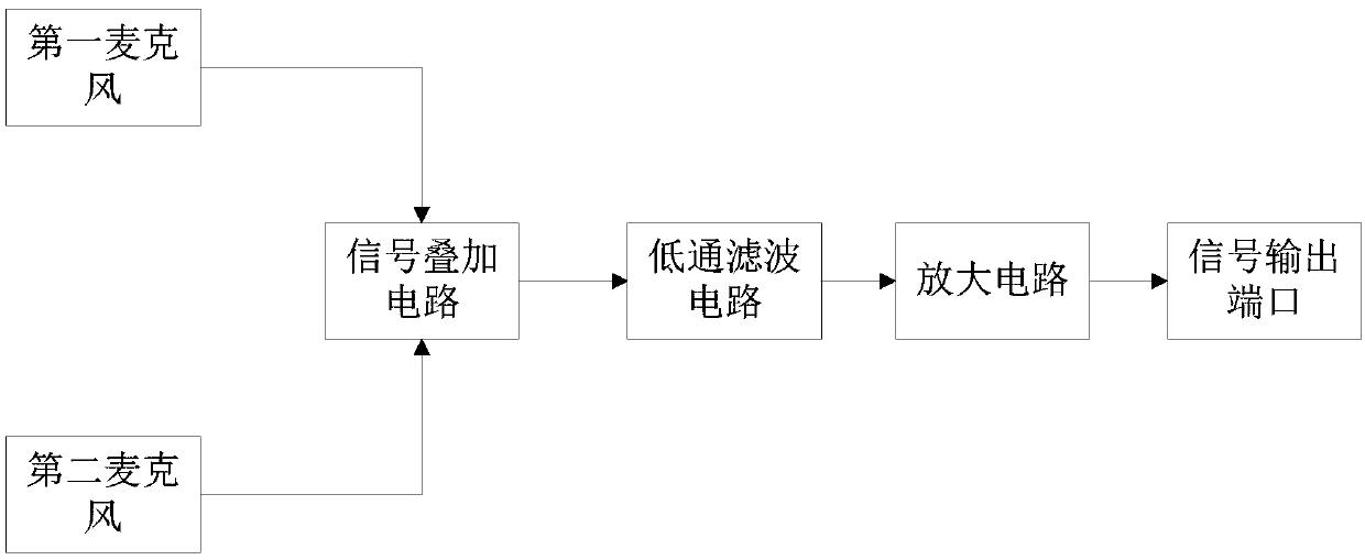
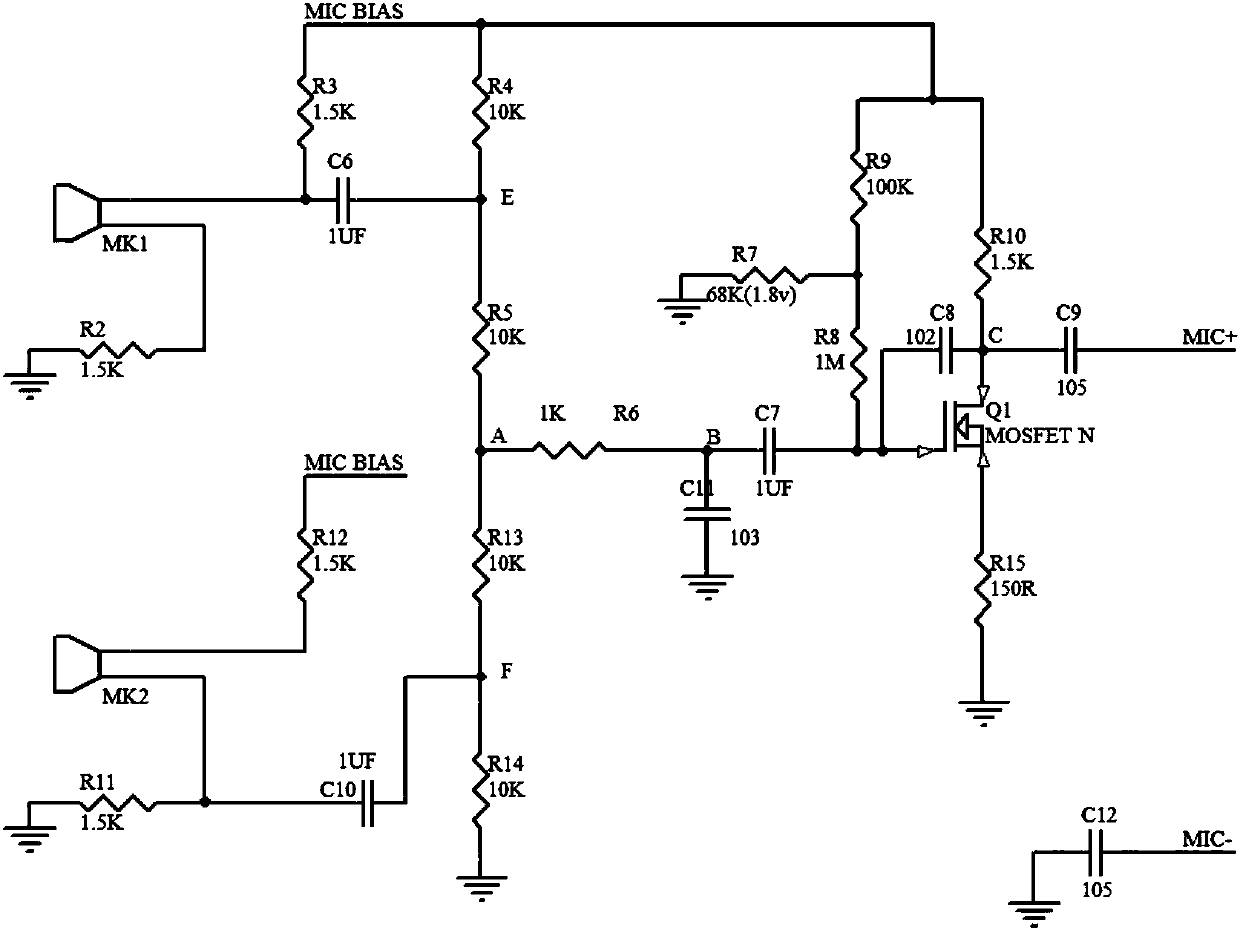
[0025] Such as figure 2 As shown, it shows the circuit principle diagram of the specific embodiment of the present invention, and each part of each circuit will be described in detail below.

[0026] The positive pole of the first microphone MK1 is connected to the power supply MIC BIAS through the resistor R3, and its negative pole is connected to the ground through the resistor R2; the positive pole of the second microphone MK2 is connected to the power supply MIC BIAS through the resistor R12, and its negative pole is connected to the ground through the resistor R11. In the embodiment, both the first microphone MK1 and the second microphone MK2 are electret microphones.

[0027] The signal superposition circuit includes a fifth resistor R5 and a thirteenth resistor R13, the anode of the first microphone MK1 is connected to the fifth resistor R5 through the sixth capacitor C6, and the other end of the fifth resistor R5 is connected to the sixth resistor R6 , the negative e...


PUM


Abstract

The invention discloses a dual-microphone noise reduction and echo elimination circuit, which comprises a first microphone, a second microphone and a signal superposition circuit. Two microphones withthe same sensitivity and the same impedance are adopted, and the two microphones are connected into two identical circuits. When the two microphones receive the same sound wave, two paths of samplingsignals are opposite in phase and the same in amplitude. The two paths of signals are overlapped with each other through the signal superposition circuit, so that the two paths of signals can be counteracted to be equivalent to the effect of an operational amplifier subtraction circuit. Due to the fact that the circuit is omitted, and the working voltage of the microphone only needs to be above 1V, the working voltage of the whole circuit is also reduced, and the overall current consumption is reduced, so that the cost is reduced, the purpose of the circuit is simplified, and the problems ofpower supply and power consumption of a dry battery powered product are solved. Due to reduction of a device, the product can be more miniaturized.

Description

technical field [0001] The invention relates to the technical field of electronic circuits, in particular to a dual microphone noise reduction and echo elimination circuit. Background technique [0002] The microphone is Mi and Mic. [0003] At present, there are mainly two processing methods for noise reduction or echo cancellation. One is through multi-channel MIC sampling and processing through software algorithms. This requires a relatively strong computing power of the CPU, high cost, and high power consumption, and is not suitable for consumer electronic products that use dry batteries. The other is hardware circuit implementation, using dual-microphone sampling, and subtracting the signals of the two MICs through a subtraction circuit composed of operational amplifiers. Most of the operational voltages of operational amplifiers on the market are above 3V, using two dry batteries Powered products can only work with new batteries, or need to add a boost chip, and the ...

Claims


Application Information

Patent Timeline
IPC IPC(8): H04R3/02H04R3/00
CPCH04R3/005H04R3/02H04M9/08
Inventor 伍泽良
Owner SHENZHEN COOPERATION TECH
Why Eureka
Try Eureka