
Integrated power module and smart power module for motor drive

An integrated power module and motor drive technology, which is applied in the direction of circuits, electrical components, and electrical solid-state devices, can solve the problems of increasing the complexity of peripheral PCB wiring, increasing production costs, and increasing the defective rate of module production, so as to achieve miniaturization and multi-function, improving production yield and efficiency, flexible chip layout and wiring effects

Pending Publication Date: 2018-02-27
HANGZHOU SILAN MICROELECTRONICS
View PDF6 Cites 9 Cited by
  • Summary
  • Abstract
  • Description
  • Claims
  • Application Information

AI Technical Summary

Problems solved by technology

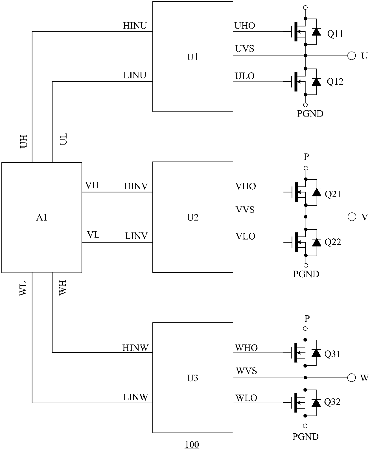
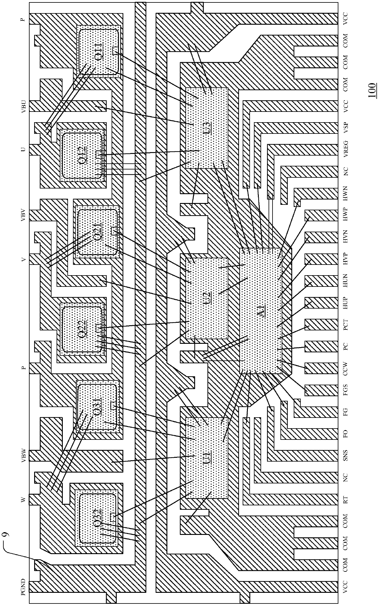
The chips are connected by wires. Therefore, inside the integrated power module 100, the number of wires is large, chaotic, miscellaneous, and long, and they are easily subjected to stress during packaging, causing problems such as wire bending, short circuit, collapse, missing wires, and wire breakage, which make the module production The defective rate increases and the production cost increases
The confusion of high-voltage pins and low-voltage pins increases the complexity of peripheral PCB routing
[0006] In addition, the first to third gate driver chips U1 to U3 of the gate driver chips in the integrated power module 100 provided in the prior art include bootstrap diodes. Due to the limitation of the production process, the resistance of the bootstrap resistors is about 300Ω. , which is more than ten times higher than that of general modules, may cause poor or slow system startup and affect system performance
[0007] Furthermore, the first to third gate driver chips U1 to U3 in the integrated power module 100 do not integrate functions such as overcurrent protection, overtemperature protection, FO alarm, etc., so that the layout design of the integrated power module 100 It cannot be used to repackage into an integrated power module that does not have a built-in motor control dedicated chip A1. If an additional low-voltage gate drive module is added, its pin wiring will be very difficult

Method used


Image

  • Integrated power module and smart power module for motor drive
  • Integrated power module and smart power module for motor drive
  • Integrated power module and smart power module for motor drive

Examples


Embodiment Construction

[0040] Hereinafter, the present invention will be described in more detail with reference to the accompanying drawings. In the various figures, identical elements are indicated with similar reference numerals. For the sake of clarity, various parts in the drawings have not been drawn to scale. Also, some well-known parts may not be shown.

[0041] In the following, many specific details of the present invention are described, such as device structures, materials, dimensions, processing techniques and techniques, for a clearer understanding of the present invention. However, the invention may be practiced without these specific details, as will be understood by those skilled in the art.

[0042] In this application, the term "high-voltage pin" refers to a pin in a chip or package structure that may appear in a high-voltage state, and the term "low-voltage pin" refers to a pin in a chip or package structure that is always in a low-voltage state.

[0043] The invention can be ...


PUM


Abstract

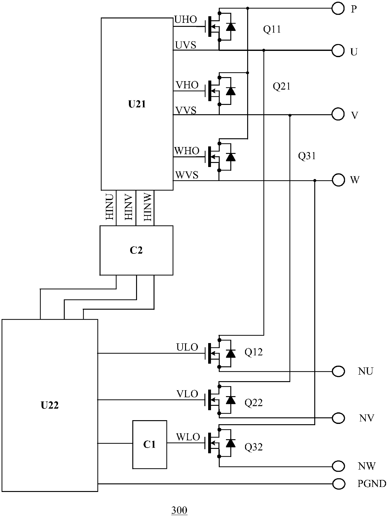
The invention discloses an integrated power module and smart power module for motor drive. The integrated power module includes a lead frame which is provided with a plurality of die pads and a plurality of pins and further includes a plurality of high-side transistors, a plurality of low-side transistors, a first gate driving chip, a second gate driving chip and an auxiliary module which are fixed to the die pads, wherein the first gate driving chip is used for providing gate driving signals for the plurality of high-side transistors, the second gate driving chip is used for providing gate driving signals for the plurality of low-side transistors, and the auxiliary module is disposed between the first gate driving chip and the second gate driving chip. The integrated power module uses theauxiliary module for improving the chip layout and routing in the integrated power module so as to improve the reliability of the integrated power module and improve the production yield and efficiency.

Description

technical field [0001] The present invention relates to the technical field of integrated semiconductors, and more specifically, to an integrated power module and an intelligent power module for driving a motor. Background technique [0002] In motor drive applications, a motor drive circuit can be used to generate three-phase drive voltages from a DC power supply to supply power to a three-phase motor. Existing motor drive circuits include a control chip, multiple gate drive chips, and a full bridge circuit composed of multiple transistors. With people's demand for high integration and miniaturization of chips, the motor drive circuit has been formed into an integrated power module to realize the integration of motor control and power drive. [0003] figure 1 and 2 A schematic circuit diagram and an internal perspective view of an integrated power module according to the prior art are shown, respectively. Such as figure 1 As shown, the existing motor drive circuit incl...

Claims


Application Information

Patent Timeline
Patent Type & Authority Applications(China)
IPC IPC(8): H01L23/31H01L23/498H01L23/495H01L25/07H01L27/02
CPCH01L23/49811H01L25/07H01L27/0207H01L23/3121H01L23/495H01L2224/48137H01L2224/48247H01L2224/49111H01L2224/49171
Inventor 李祥吴美飞
Owner HANGZHOU SILAN MICROELECTRONICS
Learn More