

Fluidized bed and molten bed combination type coal catalytic gasification reaction apparatus and fluidized bed and molten bed combination type coal catalytic gasification reaction method
A technology of fluidized bed gasification and coal catalytic gasification, which is applied in the field of coal catalytic gasification, can solve the problems of low carbon conversion rate and gasification intensity, low methane yield, poor operation stability and reliability of gasifier, etc. Achieve high carbon conversion rate, high energy utilization rate, and promote the effect of pyrolysis and methanation reaction process
- Summary
- Abstract
- Description
- Claims
- Application Information
AI Technical Summary
Problems solved by technology
Method used
Image

Examples
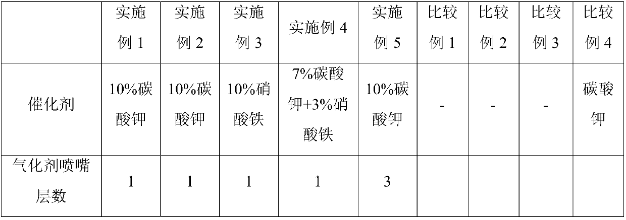
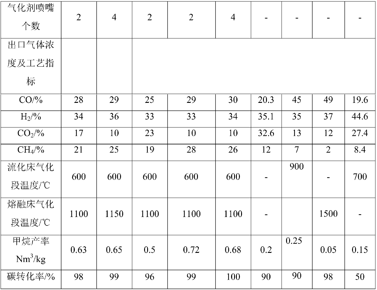
Embodiment 1
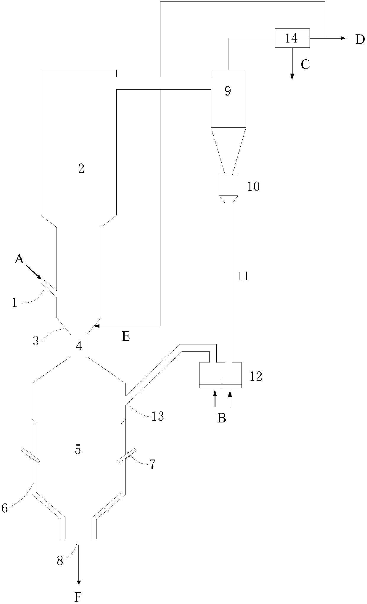
[0046] A combined fluidized bed and molten bed catalytic gasification device, the inner diameter of the dense phase section of the fluidized bed is 0.2m, the height is 5m, the inner diameter of the dilute phase section is 0.3m, and the height is 6m, and the angle between the inclined surface of the gas distributor and the horizontal plane is 30°, there are air holes on the conical surface of the gas distributor, the air holes are evenly arranged 10 times along the circumference, and the opening rate is 2%. The inner diameter of the throat is 0.1m, the inner diameter of the gasification section of the lower molten bed is 0.8m, and the height is 2m. There are two layers of gasification agent nozzles arranged at equal intervals around the periphery. The inner diameter of the slag mouth is 0.3m.
[0047] In the experiment, Inner Mongolia lignite was mixed with 10% potassium carbonate catalyst, and fed into the fluidized bed gasification section from the raw material inlet, and the...
Embodiment 2
[0049] A combined fluidized bed and molten bed catalytic gasification device, the inner diameter of the dense phase section of the fluidized bed is 0.2m, the height is 5m, the inner diameter of the dilute phase section is 0.3m, and the height is 6m, and the angle between the inclined surface of the gas distributor and the horizontal plane is 30°, there are air holes on the conical surface of the gas distributor, the air holes are evenly arranged 10 times along the circumference, and the opening rate is 2%. The inner diameter of the throat is 0.1m, the inner diameter of the gasification section of the lower molten bed is 0.8m, and the height is 2m. Four gasification agent nozzles are arranged in a layer at equal intervals around the periphery. The inner diameter of the slag mouth is 0.3m.
[0050] In the experiment, Inner Mongolia lignite was mixed with 10% potassium carbonate catalyst, and fed into the fluidized bed gasification section from the raw material inlet, and the cir...
Embodiment 3
[0052] A combined fluidized bed and molten bed catalytic gasification device, the inner diameter of the dense phase section of the fluidized bed is 0.2m, the height is 5m, the inner diameter of the dilute phase section is 0.3m, and the height is 6m, and the angle between the inclined surface of the gas distributor and the horizontal plane is 30°, there are air holes on the conical surface of the gas distributor, the air holes are evenly arranged 10 times along the circumference, and the opening rate is 2%. The inner diameter of the throat is 0.1m, the inner diameter of the gasification section of the lower molten bed is 0.8m, and the height is 2m. There are two layers of gasification agent nozzles arranged at equal intervals around the periphery. The inner diameter of the slag mouth is 0.3m.
[0053] In the experiment, Inner Mongolian lignite was selected, crushed to make pulverized coal less than 1mm and mixed with 10% ferric nitrate catalyst, and added to the fluidized bed g...
PUM
 Abstract
Description
Claims
Application Information