Inductor and manufacturing method thereof

A manufacturing method and technology of inductors, which are used in the manufacture of inductors, fixed inductors, inductors/transformers/magnets, etc., can solve the problems of limited self-resonant frequency increase, impact on product application, and blocked application range, and reduce Distributed capacitance, the effect of increasing self-resonant frequency

Pending Publication Date: 2018-03-06
SHENZHEN SUNLORD ELECTRONICS
View PDF0 Cites 12 Cited by
  • Summary
  • Abstract
  • Description
  • Claims
  • Application Information

AI Technical Summary

Problems solved by technology

[0002] As electronic devices tend to be miniaturized and high-frequency, but the self-resonant frequency has not been improved accordingly, which greatly affects the application of the product
At present, ordinary one-piece inductance devices h

Method used


Image

  • Inductor and manufacturing method thereof
  • Inductor and manufacturing method thereof
  • Inductor and manufacturing method thereof

Examples


Embodiment 1

[0025] This embodiment provides a method for manufacturing an inductor, the steps of which are described in detail as follows:

[0026] 1) Core production

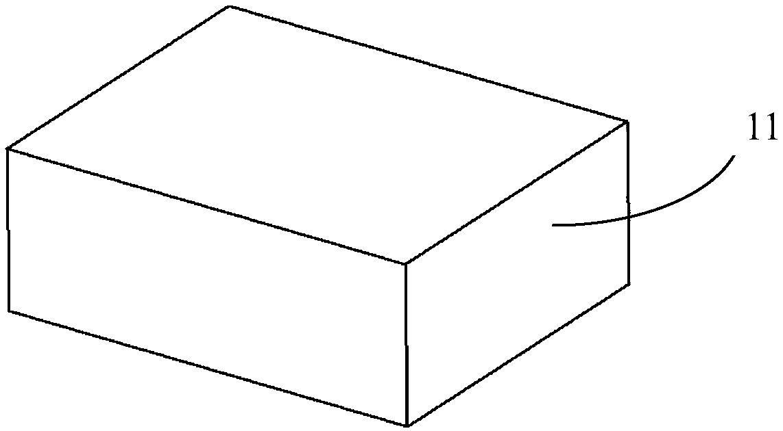
[0027] Preparation of granulated magnetic powder: the granulated magnetic powder includes magnetic powder and resin, and the mass of the resin accounts for 2%wt-5%wt of the mass of the magnetic powder. The magnetic powder can be iron alloy magnetic powder, ferrite magnetic powder or metal magnetic powder. By controlling the ratio within the range, the granulated magnetic powder can be suitable for the compression molding process. The granulated magnetic powder is pressed under a certain pressure to obtain a magnetic block 11, such as Figure 1A and 2A shown.

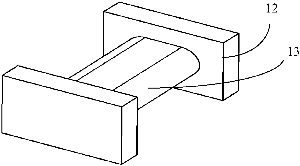
[0028] The obtained magnetic block 11 is cut into a magnetic core structure, which can be any magnetic core structure such as a dumbbell shape or an I-shape. In this example, if Figure 1B As shown, the magnetic block 11 is cut into a dumbbell-shaped magnetic co...

Embodiment 2

[0053] The difference between this embodiment and Embodiment 1 is that the coil 24 is wound with a flat wire, thereby having greater space utilization and the area of ​​the lead-out ends 27, 28, such as Figure 5 shown. The preparation process of this example is the same as that of Example 1, and will not be repeated here. In this embodiment, flat wires are used for winding, so that the damage to the flat wires during molding is less, and the risk of open and short circuit of the device is reduced. In the inductor prepared in this example, the coil has a vertical structure. Compared with the ordinary horizontal structure, the self-resonance frequency can be effectively increased, and as the size of the inductance device is gradually thinned, the increase ratio of the self-resonance frequency has a tendency to gradually increase. , suitable for the miniaturization and thinning of inductive devices.


PUM

PropertyMeasurementUnit
Thicknessaaaaaaaaaa

Abstract

The invention discloses an inductor and a manufacturing method thereof. The manufacturing method of the inductor includes the following steps: S1, manufacturing a magnetic core, pressing granulated magnetic powder into a high-density block, cutting into a magnetic core structure, and sintering to make it compact; The magnetic core includes a central column and two leaf pendulums; S2, winding the coil: winding the coil on the central column, after winding, the section of the coil is parallel to the long-height plane of the inductor, and the coil The two lead-out ends are located on both sides of the center column and are on the same plane; S3, compression molding: fill a layer of the granulated magnetic powder at the bottom of the mold for pre-compression and densification, and then place the magnetic core wound with the coil in step S2 Implantation into a mold; after implantation, filling the mold with the granulated magnetic powder for compression molding; S4, heat treatment of semi-finished products; S5, production of terminal electrodes. The inductor and its manufacturing method of the present invention have higher self-resonance frequency on the basis of obtaining an inductor with large inductance.

Description

【Technical field】 [0001] The invention relates to an inductance device and a manufacturing method. 【Background technique】 [0002] As electronic devices tend to be miniaturized and high-frequency, but the self-resonance frequency has not been improved accordingly, which greatly affects the application of the product. At present, the common one-piece inductance device has a larger coil cross-sectional area, and the same inductance requires fewer turns. However, with the development of miniaturization and thinner inductance devices, the self-resonant frequency is limited, and the application range is hindered. . [0003] The disclosure of the above background technical content is only used to assist in understanding the inventive concepts and technical solutions of the present invention, and it does not necessarily belong to the prior art of this patent application. There is no clear evidence that the above content has been disclosed on the filing date of this patent applicat...

Claims


Application Information

Patent Timeline
IPC IPC(8): H01F17/04H01F27/24H01F27/30H01F41/00H01F41/02
CPCH01F17/045H01F27/24H01F27/306H01F41/00H01F41/0246H01F2017/048
Inventor 秦浩陆达富李有云王文杰
Owner SHENZHEN SUNLORD ELECTRONICS
Why Eureka
Try Eureka