Time-to-digit conversion device and digital phase-locked loop

A time-to-digital conversion and digital technology, applied in time-to-digital converters, devices for measuring time intervals, and electrical unknown time interval measurement, etc., can solve the problems of high circuit technology and layout matching requirements, low time measurement accuracy, etc. Reduced requirements for process and layout matching, effect of high time measurement accuracy

Active Publication Date: 2018-03-13
ANYKA (GUANGZHOU) MICROELECTRONICS TECH CO LTD
View PDF11 Cites 18 Cited by
  • Summary
  • Abstract
  • Description
  • Claims
  • Application Information

AI Technical Summary

Problems solved by technology

[0004] In view of this, the embodiment of the present invention provides a time-to-digital conversion device and a digital phase-locked loop to solve the problems in the prior art that the time measurement accuracy of the time-to-digital conversion device is not high and the requirements for circuit process and layout matching are high

Method used


Image

  • Time-to-digit conversion device and digital phase-locked loop
  • Time-to-digit conversion device and digital phase-locked loop
  • Time-to-digit conversion device and digital phase-locked loop

Examples


Embodiment 1

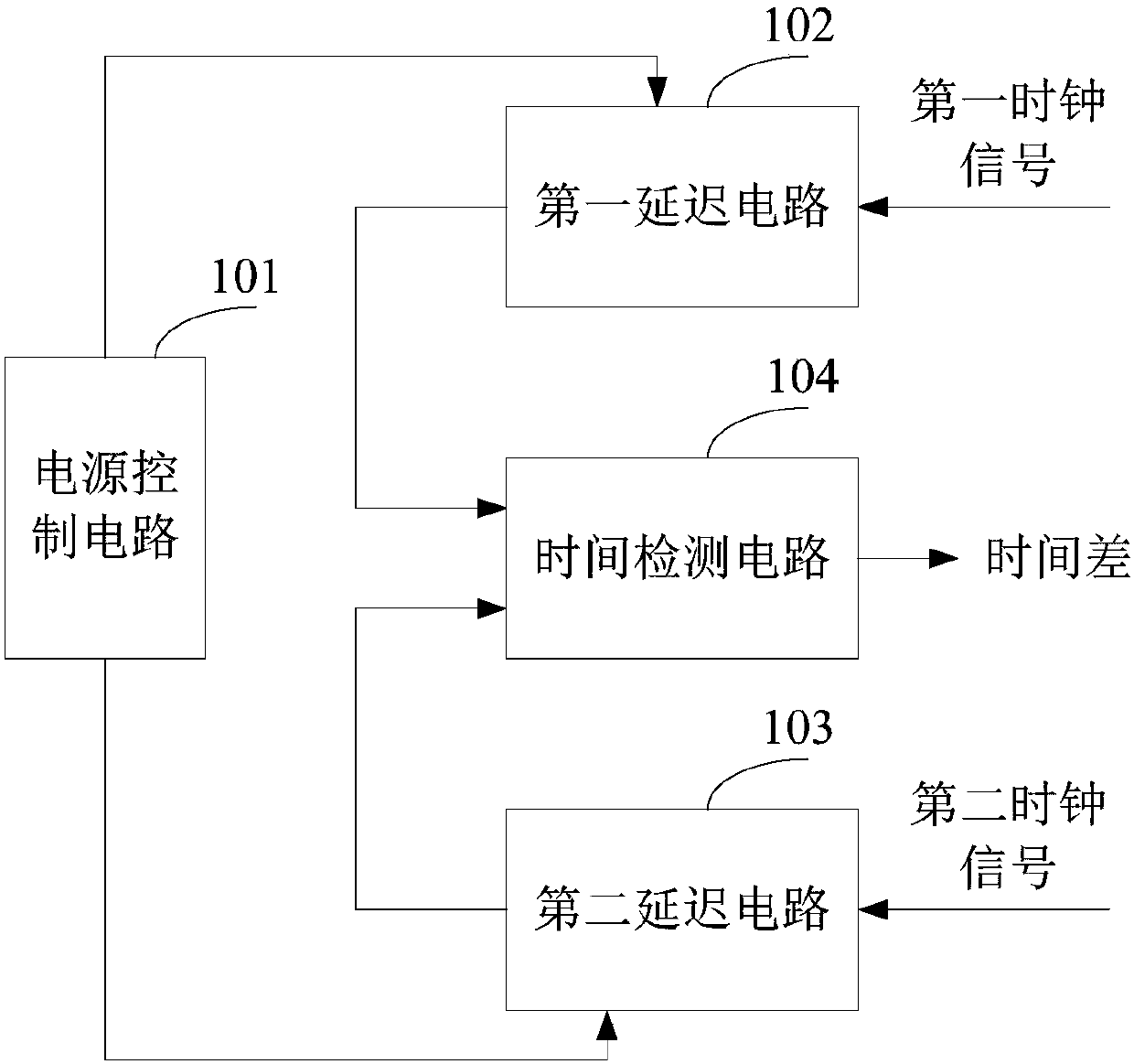
[0033] figure 1 A schematic diagram of the system structure of the time-to-digital conversion device is shown, and the details are as follows:

[0034] The time-to-digital conversion device provided by the embodiment of the present invention includes: a power control circuit 101 , a first delay circuit 102 , a second delay circuit 103 and a time detection circuit 104 .

[0035] The power control circuit 101 is provided with a first voltage output terminal and a second voltage output terminal, the first voltage output terminal is connected to the first delay circuit 102, and the second voltage output terminal is connected to the second delay circuit 103 connection; the power supply control circuit 101 is used to generate a first voltage and a second voltage, which are respectively output to the first delay circuit 102 and the second voltage output terminal through the first voltage output terminal and the second voltage output terminal. Delay circuit 103.

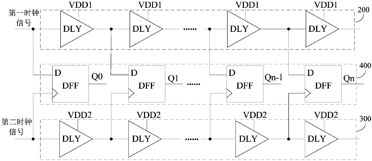
[0036] The first d...

Embodiment 2

[0056] see Figure 4 , this embodiment provides a digital phase-locked loop, including a digital loop filter 200, a digital voltage-controlled oscillator 300, and the time-to-digital conversion device 100 described in Embodiment 1; the time-to-digital conversion device 100 and the digital loop filter The digital loop filter 200 is connected to the voltage-controlled oscillator 300 , and the voltage-controlled oscillator 300 is also connected to the time-to-digital conversion device 100 .

[0057] The digital voltage-controlled oscillator 300 is configured to output an oscillator clock signal to the time-to-digital conversion device 100 .

[0058] Wherein, the output of the digital voltage controlled oscillator 300 is a pulse sequence, and the period of the output pulse sequence is controlled by the correction signal sent by the digital loop filter 200 .

[0059] The digital loop filter 200 is used to suppress the input noise in the digital phase-locked loop, and is also used ...


PUM


Abstract

The invention is suitable for the technical field of time precision measurement and provides a time-to-digit conversion device and a digital phase-locked loop. The device comprises a power supply control circuit, a first delay circuit, a second delay circuit and a time detection circuit; the power supply control circuit generates a first voltage and a second voltage and transmits the first voltageand the second voltage to the first delay circuit and the second delay circuit respectively; the first delay circuit is used for carrying out delay processing on a received first clock signal according to the first voltage; the second delay circuit is used for carrying out delay processing on a received second clock signal according to the second voltage; the time detection circuit is used for receiving the first clock signal and the second clock signal obtained after delay processing, and the time difference between the first clock signal and the second clock signal is detected. According tothe device, different voltages are input into the two delay circuits so that the two delays can be different, and higher and more stable measurement precision is obtained; meanwhile, requirements ofa circuit technology and layout are reduced.

Description

technical field [0001] The invention belongs to the technical field of precise time measurement, and in particular relates to a time-to-digital conversion device and a digital phase-locked loop. Background technique [0002] With the reduction of the chip process size, the advantages of small area and low power consumption, the all-digital phase-locked loop will gradually replace the traditional phase-locked loop. Wherein, the time-to-digital conversion device realizes the detection of the phase difference between the output frequency and the reference frequency in an all-digital phase-locked loop. The detection of the phase difference is closely related to the detection of the time difference between signals, and the accuracy of the time-to-digital conversion device determines the frequency accuracy that the all-digital phase-locked loop can achieve. [0003] At present, the commonly used time-to-digital conversion device delays the oscillator clock signal by a unit by set...

Claims


Application Information

Patent Timeline
Patent Type & Authority Applications(China)
IPC IPC(8): G04F10/00
CPCG04F10/005Y02D10/00
Inventor 潘少辉胡胜发
Owner ANYKA (GUANGZHOU) MICROELECTRONICS TECH CO LTD
Why Eureka
Try Eureka