Hydraulic servo buffer capable of achieving active control

A hydraulic servo and active control technology, applied in the field of hydraulic buffers, can solve the problems of long recovery time, complex mechanical structure, low control precision, etc., and achieve the effect of high automatic control precision, simple structure and fast response.

Active Publication Date: 2018-03-20
YANSHAN UNIV
View PDF7 Cites 13 Cited by
  • Summary
  • Abstract
  • Description
  • Claims
  • Application Information

AI Technical Summary

Problems solved by technology

This kind of hydraulic buffer has long response time, low control precision, long recovery time, and cannot control the hydraulic oil pressure after buffering, and cannot meet the requirements of high-precision, fast-response vibration reduction occasions
Another type of buffer is that the servo spool is integrated into the hydraulic cylinder. The overall action of the hydraulic cylinder is realized through the mechanical structure. The buffer response during this buffer period is fast and the precision is high, but it still cannot realize the separate circulation of the oil and requires manual work. Mechanical assistance, while converting the linear motion of the hydraulic cylinder into curved motion requires a complex mechanical structure
[0003] Now some occasions that require high control accuracy require that when the load is reduced: when the system is overloaded, the load should be reduced within a time of no more than 0.2s, but in order to meet the requirements of certain functions of the system, it is necessary to convert part of the load into acceleration and reduce the load at the same time The position of the system's load-reducing receiving part changes in a curve, and it is in a different position in the overload and normal state. It is difficult for the existing buffer to meet the action requirements of the system.

Method used


Image

  • Hydraulic servo buffer capable of achieving active control
  • Hydraulic servo buffer capable of achieving active control

Examples


Embodiment Construction

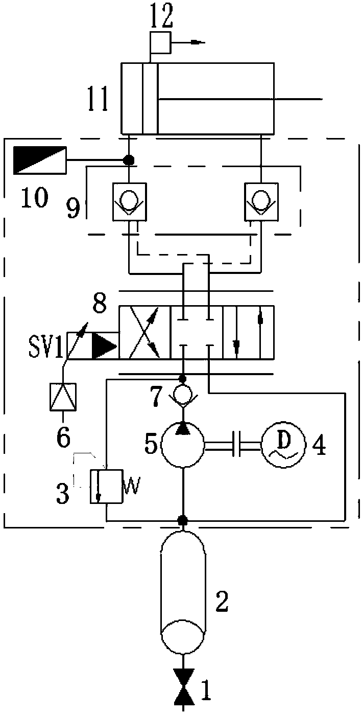
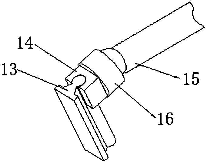
[0014] exist figure 1 with figure 2 In the active control hydraulic servo buffer shown, the low-pressure accumulator 2 is connected to the normally closed switch valve 1, said low-pressure accumulator is connected to the hydraulic quantitative pump 5 equipped with the electric motor 4, and the hydraulic quantitative pump is connected to the non-return valve 7 is connected to the inlet, the outlet of the one-way valve 7 is connected to the oil inlet of the hydraulic servo valve 8, and the oil return port of the hydraulic servo valve is connected to the outlet of the low-pressure accumulator. The outlet of the one-way valve 7 is connected with the inlet of the safety valve 3, the safety valve 3 is a direct-acting relief valve, and the outlet of the safety valve 3 is connected with the outlet of the low-pressure accumulator. The hydraulic servo valve is a three-position four-way hydraulic servo valve, which is provided with a servo amplifier 6 and an electromagnet sv1. The two...


PUM


Abstract

The invention discloses a hydraulic servo buffer capable of achieving active control. The hydraulic servo buffer is characterized in that a low-pressure energy accumulator with a switch valve is connected with a hydraulic constant delivery pump with a motor, the hydraulic constant delivery pump is connected with an inlet of a one-way valve, an outlet of the one-way valve is connected with an oil inlet of a hydraulic servo valve with a hydraulic servo amplifier, an oil return port of the hydraulic servo valve is connected with an oil outlet of the low-pressure energy accumulator, two ports of an oil outlet of the hydraulic servo valve are connected with two oil inlets of a hydraulic lock, oil outlets of the hydraulic lock are connected with a rodless cavity and a rod cavity of a hydraulic cylinder respectively, and a pressure sensor is arranged on a pipeline which enables the hydraulic lock and the rodless cavity to be connected; and a displacement sensor is arranged on a piston rod inthe hydraulic cylinder, the outer end of the piston rod of the hydraulic cylinder is hinged to a sliding block through a spherical hinge, and the sliding block is arranged on a guide rail corresponding to the sliding block. According to the hydraulic servo buffer capable of achieving active control, the responding speed and the control precision are high, specified loads are applied to a system, and then the requirements of some high-grade, precision and advanced special occasions on load reducing are achieved.

Description

technical field [0001] The invention relates to a hydraulic shock absorber, especially a servo-controlled hydraulic shock absorber. Background technique [0002] Part of the current hydraulic buffer is a combination of a hydraulic cylinder and a mechanical spring. The process of compressing the buffer is the process of squeezing the oil through the piston to do work. This process consumes a lot of kinetic energy and acts as a buffer. When the work is finished, the piston is pushed to the original position by the return spring to complete a working cycle. This kind of hydraulic buffer has long response time, low control precision and long recovery time, and cannot control the hydraulic oil pressure after buffering, and cannot meet the requirements of high precision and fast response vibration reduction occasions. Another type of buffer is that the servo spool is integrated into the hydraulic cylinder. The overall action of the hydraulic cylinder is realized through the mech...

Claims


Application Information

Patent Timeline
Patent Type & Authority Applications(China)
IPC IPC(8): F16F9/14F16F9/32F16F9/34F16F9/512F16F9/54F16F9/58
CPCF16F9/14F16F9/3292F16F9/34F16F9/5123F16F9/54F16F9/58F16F2230/06F16F2230/08F16F2230/14F16F2232/00
Inventor 赵静一李文雷茹强司少朋冯轩刘杰孙浩
Owner YANSHAN UNIV
Why Eureka
Try Eureka