Microwave signal inhibition device, method, antenna assembly and microwave ablation needle

A microwave signal and suppressing device technology, applied in the field of microwave ablation needles, can solve the problems of aggravating the carbonization degree of the ablated area, underutilization of electromagnetic energy, etc., and achieve the effect of reducing the carbonization degree

Pending Publication Date: 2018-03-23
SINOSURGICAL HEALTHCARE TECH ZHEJIANG CO LTD
View PDF1 Cites 7 Cited by
  • Summary
  • Abstract
  • Description
  • Claims
  • Application Information

AI Technical Summary

Problems solved by technology

The electromagnetic wave will be absorbed in a large amount when passing through the ablation area, but the energy of the electromagnetic wave entering the peripheral extended ablation area is very little, which leads to the insufficient use of electromagnetic energy in the extended ablation area, and instead increases the degree of carbonization of the ablation area

Method used


Image

  • Microwave signal inhibition device, method, antenna assembly and microwave ablation needle
  • Microwave signal inhibition device, method, antenna assembly and microwave ablation needle
  • Microwave signal inhibition device, method, antenna assembly and microwave ablation needle

Examples


Embodiment

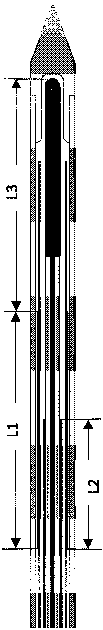
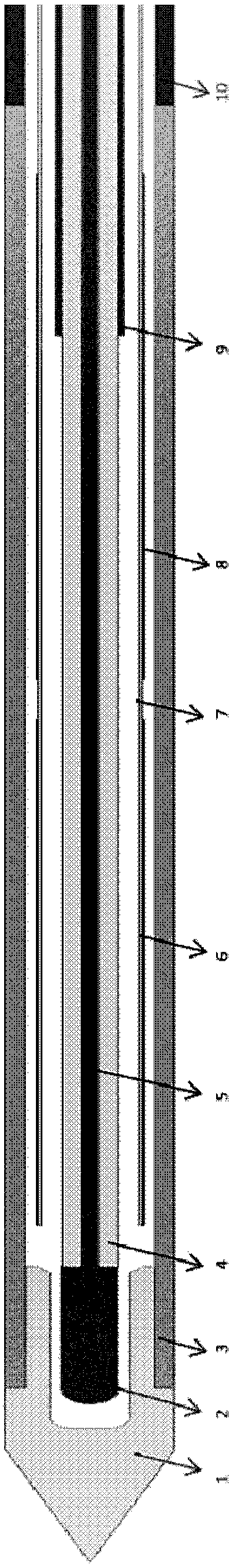
[0050] The profile of the multi-stage choke microwave ablation antenna assembly of the present invention is as follows figure 2 As shown, it includes ceramic needle head 1, copper cap 2, non-metallic outer tube 3, coaxial line dielectric layer 4, coaxial line inner conductor 5, first section of copper foil 6, PI water inlet pipe 7, second section of copper foil 8 , 9 coaxial outer conductors, 10 stainless steel outer tubes.

[0051] The internal blank area is the cooling water circulation channel, and the copper cap is welded on the inner conductor of the coaxial line. The length of the copper cap is about 1 / 10 to 1 / 2 wavelength (relative to the tissue dielectric constant). The length of each section of copper foil wrapped on the PI tube is about half a wavelength (relative to the tissue dielectric constant), and forms a multi-section composite ring structure with the PI tube, and the distance between each section of the composite structure is about 1 / 10 to 1 / 20 wavelengths...


PUM


Abstract

A microwave signal inhibition device and method, an antenna assembly and a microwave ablation needle are provided. The microwave signal inhibition device comprises a composite structure. The compositestructure comprises non-metallic material with a low dielectric constant, and a plurality of metal thin films formed on the non-metallic material, wherein the length of each section of the metal thinfilm is one fourth to three fourths of wavelength of a to-be-inhibited microwave signal; an interval between the metal thin films is one tenth to one twentieth of wavelength of the to-be-inhibited microwave signal; and a relative dielectric constant of the non-metallic material with the low dielectric constant relative to vacuum is less than or equal to 5. The microwave signal inhibition device and the microwave ablation needle based on multi-stage choke flow technology have great self-adaptivity; upon small input power or short ablation time, or power decrease or ablation time reduction, anideal spherical ablation area can be achieved; and compared with a common design, microwave energy can be fully utilized and carbonization degree of a central area can be reduced.

Description

technical field [0001] The present invention relates to the technical field of microwave treatment equipment, and more specifically relates to a microwave signal suppressing device and method, an antenna assembly for microwave ablation and a microwave ablation needle using the same. Background technique [0002] Since the first report in 1994 that ultrasound-guided percutaneous puncture was successful in the treatment of small liver cancer by implanting microwave antennas into tumors, microwave ablation technology has developed rapidly through continuous improvement and innovation of microwave instruments and antennas. Early microwave ablation needles did not have a water-cooling circulation system, and the needle shaft was easily overheated, and could only support a small power input of 10-30W. The width of the in vitro ablation area was only 1-2 cm, and the shape was irregular. The application of the water-cooled circulation system makes the temperature of the microwave ne...

Claims


Application Information

Patent Timeline
Patent Type & Authority Applications(China)
IPC IPC(8): A61B18/18
CPCA61B18/1815A61B2018/00696A61B2018/00577A61B2018/00059A61B2018/00023
Inventor 黄文星詹德志
Owner SINOSURGICAL HEALTHCARE TECH ZHEJIANG CO LTD
Why Eureka
Try Eureka