Cardiotachometer

A heart rate meter and resistance technology, applied in the field of heart rate measurement devices, can solve the problems of poor electrode contact, susceptibility to electromagnetic interference, and low accuracy, and achieve the effects of low cost, reliability, and stable operation.

Inactive Publication Date: 2018-04-03
邵立新
View PDF0 Cites 1 Cited by
  • Summary
  • Abstract
  • Description
  • Claims
  • Application Information

AI Technical Summary

Problems solved by technology

The former is low in cost, but the accuracy rate is also low; the latter can achieve a high accuracy rate with the help of sophisticated and large electrocardiogram equipment, but it is susceptible to electromagnetic interference, and sometimes there may be poor contact between the electrodes and the human body, resulting in distortion of the results. The important thing is that it is not easy to carry

Method used


Image

  • Cardiotachometer

Examples


Embodiment

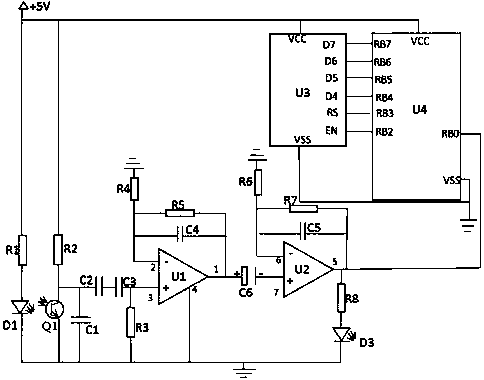
[0022] Example: such as figure 1 As shown, the heart rate meter of this embodiment includes a signal acquisition circuit, a filter circuit, an operational amplifier circuit, a processing module U4 and a display module U3;

[0023] The signal acquisition circuit includes an infrared emitting diode D1, an infrared receiving transistor Q1 and a resistor R1; the infrared emitting diode D1 and the infrared receiving transistor Q1 can be selected from the infrared emitting diode and the infrared receiving transistor in the prior art;

[0024] The filter circuit includes a resistor R2, a resistor R3, a capacitor C1, a capacitor C2, and a capacitor C3;

[0025] The operational amplifier circuit includes an operational amplifier U1, an operational amplifier U2, a resistor R4, a resistor R5, a resistor R6, a resistor R7, a capacitor C4, a capacitor C5, and a capacitor C6;

[0026] Described processing module U4 is the PIC16F84 single-chip microcomputer in the prior art;

[0027] The d...


PUM


Abstract

The present invention proposes a heart rate meter, including a signal acquisition circuit, a filter circuit, an operational amplifier circuit, a processing module U4, and a display module U3; the signal acquisition circuit includes an infrared emitting tube D1, an infrared receiving tube Q1, and a resistor R1; the filter circuit includes a resistor R2 , R3, capacitors C1, C2, and C3; the operational amplifier circuit includes operational amplifier U1, operational amplifier U2, resistors R4, R5, R6, R7, capacitors C4, C5, and C6; the processing module U4 is a PIC16F84 microcontroller; the display module U3 is an LCD1602 Display modules. Compared with the prior art, the advantages and positive effects of the present invention are: the circuit structure is simple, the response is fast, the cost is low, the operation is stable, the heart rate of the subject can be measured quickly and conveniently at low cost, and it is easy to carry; The integrated anti-interference structure can filter out most of the high-frequency interference and ensure the reliability of the measurement results.

Description

technical field [0001] The invention relates to a heart rate measuring device, in particular to a heart rate meter. Background technique [0002] Heart rate is an important indicator of human body function. A lower than normal heart rate is called bradycardia, and a higher heart rate is called tachycardia. During sports training, fitness or physical examination, people often use the results of heart rate measurement to evaluate the current state of the human body. At present, the methods for measuring the heart rate in the prior art mainly include the pulse method and the electrocardiogram method. The former is low in cost, but the accuracy rate is also low; the latter can achieve a high accuracy rate with the help of sophisticated and large electrocardiogram equipment, but it is susceptible to electromagnetic interference, and sometimes there may be poor contact between the electrodes and the human body, resulting in distortion of the results. The important thing is that ...

Claims


Application Information

Patent Timeline
Patent Type & Authority Applications(China)
IPC IPC(8): A61B5/024A61B5/00H03H5/00H03F3/68
CPCA61B5/02416A61B5/7203A61B2560/0204H03F3/68H03H5/00
Inventor 邵立新
Owner 邵立新
Why Eureka
Try Eureka