Lifetime prolonging method for crankshaft bending upsetting forming die

A technology for forming molds and bending, which is used in manufacturing tools, forging/pressing/hammer devices, forging/pressing/hammering machines, etc. It can solve the problem of poor stress conditions of thin-walled structures, affecting product production progress, and poor mold working conditions. and other problems, to achieve the effect of improving the working conditions of continuous high temperature and high load, outstanding flexibility, and improved impact toughness

Active Publication Date: 2018-04-06
NO 59 RES INST OF CHINA ORDNANCE IND
View PDF6 Cites 5 Cited by
  • Summary
  • Abstract
  • Description
  • Claims
  • Application Information

AI Technical Summary

Problems solved by technology

[0002] The bending upsetting method to manufacture the crankshaft is one of the hotspots in the crankshaft manufacturing technology of large engines at present. Compared with the traditional hot die forging integral mold structure, the mold structure is a multi-layer split combination type. The combined structure can improve the mold bearing capacity and reduce the Mold material cost, convenient mold repair and short cycle; however, due to the force characteristics of the bending and upsetting forming mold, the working conditions of the mold are extremely harsh, and the same cavity is heated repeatedly, and it is also affected by thermal expansion and cold contraction under complex alternating loads. , thermal fatigue, wear and other effects, the thin-walled structure is subjected to extremely harsh stress conditions when upsetting the crank throw, and is subjected to various loads of extrusion and bending, and the same cavity repeatedly bears large loads
A pair of molds often needs to be replaced after only dozens of pieces in service life, and the mold change cycle is long and expensive, which seriously affects the production progress of the product
In order to improve the life of the mold, the existing process often designs multiple pre-forming to improve the working condition of the mold, but this method does not fundamentally solve the problem of mold force, and it also complicates the process and makes process control more difficult

Method used


Image

  • Lifetime prolonging method for crankshaft bending upsetting forming die
  • Lifetime prolonging method for crankshaft bending upsetting forming die
  • Lifetime prolonging method for crankshaft bending upsetting forming die

Examples


Embodiment 1

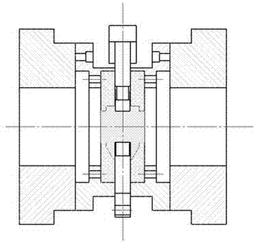
[0040] A method for extending the life of an RSV92-C crankshaft bending upsetting forming die, comprising the following steps:

[0041] 1. Forge the H13 steel ingot with a forging ratio of 3.7 to the approximate size of the mold core of φ500mm×130mm;

[0042] 2. Anneal the core forging blank at a temperature of 1050°C±20°C;

[0043] 3. Reserve 2mm for the annealed mold core forging blank according to the cavity size to the mold core size;

[0044] 4. The rough-processed mold core shall be processed according to the "double cycle quenching + tempering (1160℃±20℃×1h quenching + 600℃×2h tempering) + (1040℃±20℃×1h quenching + 600℃×2h quenching) Fire)" process for quenching and tempering;

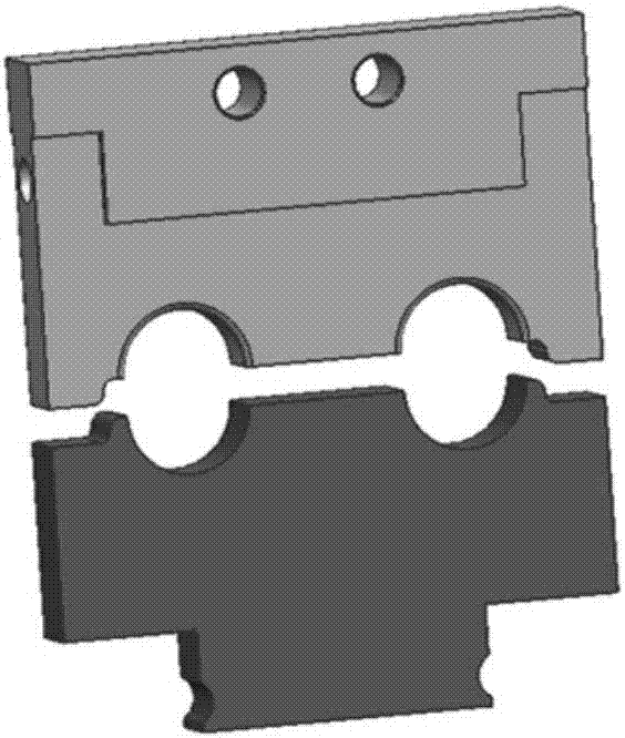
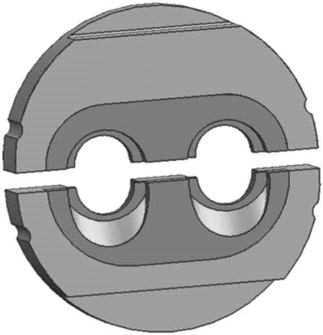
[0045] 5. The quenched and tempered mold core is finished according to the size of the cavity, and the two cavities have the same size and are symmetrically distributed along the center;

[0046] 6. Double surface strengthening treatment is carried out on the finished mold by surface nitridin...

Embodiment 2

[0053] A method for extending the life of a JDB26-C crankshaft bending upsetting forming die, comprising the following steps:

[0054] 1. Forge the H13 steel ingot with a forging ratio of 3.6 to the approximate size of the mold core of φ500mm×150mm;

[0055] 2. Anneal the core forging blank at a temperature of 1050°C±20°C;

[0056] 3. Reserve 2mm for the annealed mold core forging blank according to the cavity size to the mold core size;

[0057] 4. The rough-processed mold core shall be processed according to the "double cycle quenching + tempering (1160℃±20℃×1h quenching + 600℃×2h tempering) + (1040℃±20℃×1h quenching + 600℃×2h quenching) Fire)" process for quenching and tempering;

[0058]5. The quenched and tempered mold core is finished according to the size of the cavity, and the two cavities have the same size and are symmetrically distributed along the center;

[0059] 6. Double surface strengthening treatment is carried out on the finished mold by surface nitriding ...


PUM


Abstract

The invention discloses a lifetime prolonging method for a crankshaft bending upsetting forming die. The die of a crankshaft is designed to be of a split-type combined structure, and a crankshaft dieworking part is composed of a plurality of modules of a bending die, a positioning die, a forming die body, an anti-thrust die and the like. The forming die body is formed by inlaying of a die sleeveand a die core, and the structure of a forming party is designed to be two symmetrically-distributed cavities which alternately work to bear the high-temperature and high-loading effects, and meanwhile, the die core part is subjected to strengthening heat treatment. When the die conducts the forming work, firstly, a heated first crank throw blank is put into the one of the die symmetrical cavities, after die assembly, bending upset-extruding forming of the first crank throw blank is finished, then a manufactured piece is taken out, oxide skins in the cavities are blown away through nozzles, and lubricating heat-insulating agents are sprayed into the die cavities. According to the lifetime prolonging method, the crankshaft bending upsetting forming die can continuously work till two thousand or more pieces are manufactured, the production cost is greatly reduced, the production efficiency is improved, the processing working procedure is simple, and the lifetime prolonging method is easyto apply and popularize.

Description

technical field [0001] The invention relates to the technical field of precision plastic forming, in particular to a method for extending the life of a crankshaft bending and upsetting forming die. Background technique [0002] The bending upsetting method to manufacture the crankshaft is one of the hotspots in the crankshaft manufacturing technology of large engines at present. Compared with the traditional hot die forging integral mold structure, the mold structure is a multi-layer split combination type. The combined structure can improve the mold bearing capacity and reduce the Mold material cost, convenient mold repair and short cycle; however, due to the force characteristics of the bending and upsetting forming mold, the working conditions of the mold are extremely harsh, and the same cavity is heated repeatedly, and it is also affected by thermal expansion and cold contraction under complex alternating loads. , thermal fatigue, wear and other effects, the thin-walled...

Claims


Application Information

Patent Timeline
Patent Type & Authority Applications(China)
IPC IPC(8): B21K1/08B21J13/02C21D1/25C21D1/26C23C14/48
CPCB21J13/02B21K1/08C21D1/25C21D1/26C23C14/48
Inventor 康凤赵祖德陈强林军胡传凯夏祥生
Owner NO 59 RES INST OF CHINA ORDNANCE IND
Why Eureka
Try Eureka